
Installation manual


Connecting the control-wire cables > Connecting the UPS units in parallel
34020846EN/AE - Page 50
1. Installation
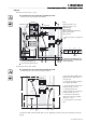
Connect the components specific to the 2000 kVA light SSC
Block diagram
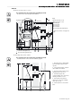
Connect the customer current sensors
UPS cabinet (1)
2000 light SSC (2)
Downstream coupling cabinet (3)
Customer current sensors (4)
This operation must be carried out by qualified personnel.
The door must be open.
The cables (not supplied) must be twisted pairs of 0.8 to 1 mm² AWG18 gauge wire with a maximum length of 100 m.
Auxiliary wires (TI) and power cables must be separated to ensure sufficient insulation for the auxiliary wires.
Once outside the cabinet, the cables must follow the earth connections between the cabinets.
Key:
(1) UPS current sensor terminal block
Suitable current sensors must be used to ensure correct operation of the installation. Please contact your technical helpline
to select the correct customer current sensors.
Recommendations: TI 4000/1, class 1, 10 VA.
Take care to respect polarity when wiring customer current sensors.
Key:
(1) Phase 1 customer current sensor
(2) Phase 2 customer current sensor
(3) Phase 3 customer current sensor
1 - Connect the terminal block connectors to the customer current sensors in the customer connection panel.
Bypass AC
1
1
3
Q5N
ext
Q4S ext
2
Q3BP
ext
4
Load
1
5
4
3
2
1
6
5
4
3
2
1
S1
S2
1
S1
S2
2
S1
S2
3
P1
P2
P1
P2
P1
P2
Terminal block
2000 light SSC cabinet
Downstream
Load
Load
Load
coupling cabinet
UPS UPS UPS