
Installation manual


Connecting the control-wire cables > Connecting the UPS units in parallel
34020846EN/AE - Page 48
1. Installation
Connecting the modular UPSs with the external bypass
This operation must be carried out by qualified personnel.
The door must be open.
The supplied cables are 10 m or 20 m long; for oher lenghts, please consult us (the maximum total length must not exceed
180 m).
Auxiliary wires (exchange, CAN and bypass cabinet) and power cables must be separated to ensure sufficient
insulation for the auxiliary wires.
Once outside the cabinet, the cables must follow the earth connections between the cabinets.
The handle of the Q3BP switch (in
the OFF position) on all UPS units
must be removed.
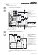
UPS cabinet
Key:
(1) Connectors
(2) Cable ties
(3) Exchange-current and CAN and
control-wire cables
Bypass cabinet
Key:
(1) Connectors
(2) Cable ties
(3) Control-wire cables
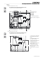
Connection with bypass cabinet:
Control-wires:
0.5 to 1.5 mm² / AWG20 to AWG16
1 - Connect the common, Q3BP ext
and Q5N ext terminals on the terminal
block in the external bypass cabinet to
connector XM4 in UPS 4 and XM5 in
UPS 1 (cables not supplied)
Exchange current:
2 - Create a loop between XM2 and
XM3 connectors in the four UPS units.
All the connectors must be used.
CAN:
3 - Fit a blue plug on connector XM6 in
UPS 1.
4 - Interconnect the XM6 and XM7
connectors in the four UPS units.
5 - Fit a red plug on connector XM7 in
the UPS 4.
Q1 Q4S Q3BP Q5N
3
2
2
2
1
XM2
XM3
XM4
XM5
XM6
XM7
1
3
2
2
1
1
Q5N ext
Q3BP ext
2
3
4
5
6
COM
2
XM7
XM6
XM3
XM2
XM6
XM3
XM2
1
Q5N ext
Q3BP ext
2
3
4
5
6
COM
1
1
2 2 2
XM7
XM7
XM5
XM5
2
3
4 4 4
XM 4 / XM 5
COM
Q3BP ext
Q5N ext
5
1
4
XM4
Q5N customer
UPS 1 UPS 2 UPS 3
UPS 4
Cabinet
bypass
external
Q5N customer