
Installation manual


Connect the backfeed option >
34020846EN/AE - Page 45
1. Installation
1.9 Connect the backfeed option
The backfeed option on normal and bypass AC inputs is compulsory if IEC 62040-1-2 is to be complied with.
Block diagram
Connecting the power cables
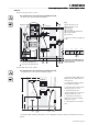
Connecting the Normal AC line backfeed cabinet
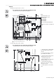
Connecting the Bypass AC line backfeed cabinet
This operation must be carried out by qualified personnel.
The door must be opened using the Ronis 405 key.
Key:
(1) Front face protective cover
(2) Neutral bar
(3) Earthing bar
(4) To the earth
(5) To normal or bypass AC line
(6) To the UPS
Diameter of backfeed cabinet
connection terminal holes: 13 mm.
1 - Remove protective cover (1)
2 - Connect the protective conductor (PE or PEN) to the earth bar (3)
3 - Connect the normal AC conductors taking care to respect the following order: L1, L2, L3 (6)
4 - Connect the UPS conductors in the following order: L1, L2, L3 (7)
5 - Refit the protective cover
1 - Remove protective cover (1)
2 - Connect the protective conductor (PE or PEN) to the earth bar (3)
3 - Connect the neutral conductor to the neutral bar (2)
4 - Connect the AC Bypass conductors in the following order: L1, L2, L3 (6)
5 - Connect the UPS conductors in the following order: L1, L2, L3 (7)
6 - Refit the protective cover
Normal AC Normal AC
Bypass AC Bypass AC
Backfeed
UPS
Backfeed
UPS
A
1
590
740
5
2
4 6
A
358
495
3
Right-hand view
Front view
Front view
.