
Installation manual


Connecting the power cables >
34020846EN/AE - Page 27
1. Installation
1.6 Connecting the power cables
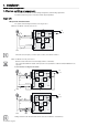
Single or modular UPS cabinet
160 to 400 kVA
Remove the protective covers
Dimensions are indicated in millimetres.
For parallel installations with no neutral on the load and the network, interconnect the UPS neutrals.
This operation must be carried out by qualified personnel.
The door must be opened using the Ronis 405 key.
Key:
(1) Protective covers
(2) Tie bar
(3) To normal AC line
(4) To the batteries
(5) To bypass AC line
(6) To the earth
(7) To the load
(8) Earthing bar
1 - Remove the protective covers (1)
Connecting the power cables
This operation must be carried out by qualified personnel.
See “Characteristics of the connection terminals”, page 20.
1 -Check that switches Q1, Q4S,
Q3BP and Q5N are in the OFF
position as shown opposite.
2 - Connect the protective conductor
(PE or PEN) to the earth bar
3 - Connect the normal AC conductors
taking care to respect the following
order: L1, L2, L3
4 - Connect the bypass AC
conductors taking care to respect the
following order: N*, L1, L2, L3
5 - Connect the load conductors
taking care to respect the following
order: N*, L1, L2, L3
6 - Connect the battery
7 - Tie the cables down
8 - Connect the control-wire cables (
See “Connecting the control-wire
cables”, page 46.)
9 - Put the protective covers back in
place.
* SLT upstream TNC, downstream TNC, TNS or TT, See “Adapting the cabinet according to the neutral point connection”,
page 26.
Connections through the top of the cabinets are possible using an auxiliary cabinet 400 mm wide.
2
8
1
3 4 5 7
6
350
410
470
L1 L2 L3
+
-
260
390
N L1 L2 L3 N L1 L2 L3
Q1 Q4S Q3BP Q5N
OFF OFF OFF OFF
Normal AC Bypass ACBattery Load
Earth