
Instruction manual


Pg.10 – Instructions Version 1.1, January 2009
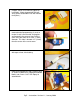
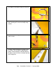
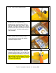
21. Install screws into tailwheel bracket.
22. Turn on radio. Make sure the Elevator and
Rudder trims are centered and all
programming is reset to neutral. Drill the
outer servo arm hole out to 3/64” (1.2mm)
diameter. This hole is located 1/2” (13mm)
from the center of the servo screw. Install on
pushrod “z-bend” and slide each pushrod
into guide tube.
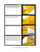
23. Install servo arms at 90º to pushrod as
shown in photo. Secure with servo arm
screw. Mount your receiver with double-
sided foam tape or Velcro.
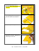
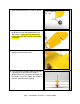
24. Install control horns and clevis using the
same technique as the ailerons. Note the
elevator pushrod (short) is on the right side
and the rudder pushrod (long) is on the left.
We recommend using a clevis safety device
fabricated from scrap fuel tubing, heat shrink
tubing, or tape to prevent all plastic clevises
from opening accidentally.