User's Manual AXFA11G Magnetic Flowmeter Remote Converter [Hardware Edition/Software Edition] IM 01E20C01-01E IM 01E20C01-01E 5th Edition Yokogawa Electric Corporation
CONTENTS Contents 1. INTRODUCTION ................................................................................................... 1-1 1.1 1.2 1.3 2. HANDLING PRECAUTIONS ............................................................................... 2-1 2.1 2.2 2.3 2.4 3. Installation Location ........................................................................................ 3-1 Mounting .........................................................................................................
CONTENTS 6. PARAMETER DESCRIPTION ............................................................................ 6-1 6.1 6.2 6.3 6.4 Parameters ....................................................................................................... 6-1 Parameter Lists ................................................................................................ 6-1 Parameter List Overview ................................................................................ 6-2 Parameter Description ...........
CONTENTS 9. ACTUAL OPERATION ......................................................................................... 9-1 9.1 10. Pre-operation Zero Adjustment ....................................................................... 9-1 9.1.1 Zero Adjustment Using Display Unit Switches ....................................... 9-2 9.1.2 Zero Adjustment via External Status Input .............................................. 9-3 MAINTENANCE .................................................................
1. INTRODUCTION 1. INTRODUCTION This instrument has been adjusted at the factory before shipment. ments. If this instrument is used in a manner not specified in this manual, the protection provided by this instrument may be impaired. • Yokogawa will not be liable for malfunctions or damage resulting from any modification made to this instrument by the customer. • The following safety symbol marks are used in this user's manual and instrument.
1. INTRODUCTION 1.1 Using the Magnetic Flowmeter Safely (4) Maintenance • Maintenance on the magnetic flowmeter should be performed by expert engineer or skilled personnel. No operator shall be permitted to perform any operations relating to maintenance. • Always conform to maintenance procedures outlined in this manual. If necessary, contact Yokogawa. • Care should be taken to prevent the build up of dirt, dust or other substances on the display panel glass or data plate.
1. INTRODUCTION 1.3 Combination Remote Flowtubes IMPORTANT • The AXFA11 Magnetic Flowmeter Converter should be used in combination with the following remote flowtubes: AXFA11G ⇔AXF002 -N to AXF26L -N Contact Yokogawa before using it in combination with flowtubes other than those listed above. • The model AXF C remote flowtube with optional code JF3 (TIIS flame proof type) cannot be combined with the AXFA11 converter. In this case, use the AXFA14 converter.
2. HANDLING PRECAUTIONS 2. HANDLING PRECAUTIONS This instrument has been inspected carefully at the factory before shipment. When the instrument is delivered, visually check that no damage has occurred during transportation. 2.3 Storage Precautions Read this section carefully as it contains important information on handling this instrument. Refer to the relevant sections for information not contained in this section. If you have any problems or questions, please contact Yokogawa sales office.
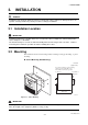
3. INSTALLATION 3. INSTALLATION WARNING Installation of the magnetic flowmeter must be performed by expert engineer or skilled personnel. No operator shall be permitted to perform procedures relating to installation. 3.1 Installation Location IMPORTANT Install the instrument in a location where it is not exposed to direct sunlight. For ambient temperature, refer to Chapter 11 “OUTLINE”. The instrument may be used in an ambient humidity where the RH ranges from 0 to 100%.
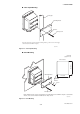
3. INSTALLATION 2-inch Pipe Mounting 2-inch pipe Mounting fixture Washer Clamp screw Pass the four clamp screws through the mounting fixture, position it on the 2-inch pipe, and then fasten the AXFA11 in place. F0302.EPS Figure 3.2.2 2-inch Pipe Mounting Panel Mounting Unit: mm (approx. inch) 203 (8.0) Panel cutout Mounting fixture 172 (6.8) R3MAX Washer Screw Clamp screw Fit the AXFA11 into the panel.
4. WIRING 4. WIRING four-core cables are used for wiring. Keep conduits or flexible tubes watertight using sealing tape. • Ground the remote flowtube and the converter separately. • Cover each shield of the signal cable with vinyl tube or vinyl tape to avoid contact between two shields or between a shield and a case. • When waterproof glands or union equipped waterproof glands are used, avoid tightening the glands with an excessive torque. • Be sure to turn power off before opening the cover.
4. WIRING 6 to 12mm (0.24 to 0.47 in.) for optional code EP Nominal Cross Section (Single wire): 0.5 to 2.5 mm2 Nominal Cross Section (Stranded wire): 0.5 to 1.5 mm2 C 90 (3.54) Black Red EX1 EX1 EX2 150 5 (5.9) 8 (0.3) max. 20 (0.8) Crimp Terminal 10.5 (0.4) L (Specified Dimensions) Unit : mm (approx. inch) On the flowtube side EX2 B 90 (3.54) 60 (2.36) C 70 (2.76) (5.9) 8(0.3) max.
4. WIRING (1) When there are no particular optional specifications The wiring port is sealed with a cap (not water-proof) that must be removed before wiring. At this time, handle the wiring port in accordance with the JIS C0920-1982 mentioned above. (2) Wiring using waterproof glands IMPORTANT Plastic gland F0406.EPS To prevent water or condensation from entering the converter housing, waterproof glands are recommended. Do not over-tighten the glands or damage to the cables may result.
4. WIRING 4.4 Wiring Connections 4.4.1 Removing Cover While supporting the front of the cover with your hand, flip the connecting screw protective cover over, and remove the four connecting screws. F0409.EPS Figure 4.4.1 Removing the Front Cover 4.4.2 Terminal Configuration When the cover is removed, the connection terminals will be visible. The terminal configuration labels are attached in the position shown in Figure 4.4.2.
4. WIRING 4.4.4 IMPORTANT DC Power Connection When using DC power as the power supply for the converter, give attention to the following points. Do not wire the terminal without terminal symbols in terminal layout labels. (1) Connecting Power Supply IMPORTANT 4.4.3 Precautions for Wiring of Power Supply Cables Do not connect power supply with reversed polarities. L/+ terminal: connect + N/– terminal: connect – When connecting to the power supply, observe the points below.
4. WIRING 4.4.5 Grounding 4.4.6 CAUTION Wiring the Remote Flowtube with the AXFA11 Converter WARNING Be sure to connect the protective grounding of the AXFA11 with a cable of 2mm2 or larger cross section in oder to avoid electrical shock to the operators and maintenance engineers and to prevent the influence of external noise. Connect the grounding wire to the mark (100 or less). Before wiring, be sure that the power supply for AXFA11 converter has been turned off to prevent an electrical shock.
4. WIRING (4) Connection with the Remote Flowtube (General-Purpose Use, Submersible Type, Size 1100 to 2600 mm (44 to 104 in.)) Connect wiring as shown in the figure below. In case of explosion proof type for CENELEC ATEX, FM, and CSA certification, connect wiring as shown in the figure below. In case of the explosion proof type, the protective grounding of remote flowtube must be connected to a suitable IS grounding system. In that case, (functional grounding terminal) need not be connected.
4. WIRING Pulse Output AXFA11 PULSE OUT IMPORTANT • As this is a transistor contact (insulated type), give attention to proper voltage and polarity when wiring. • Do not apply a voltage larger than 30V DC or a current larger than 0.2A in order to prevent damage to the instrument. • When input filter constant of the electronic counter is large in relation to the pulse width, the signal will decrease and the count will not be accurate.
4. WIRING Status Output / Alarm Output AXFA11 Protective diode AL+ IMPORTANT Load AL- Since this is an isolated transistor output, be careful of voltage and polarity when wiring. Do not apply a voltage larger than 30V DC or a current larger than 0.2A in order to prevent damage to the instrument. This output cannot switch an AC load. To switch an AC load, an intermediate relay must be inserted as shown in Figure 4.4.13 or Figure 4.4.14.
5. BASIC OPERATING PROCEDURES 5. BASIC OPERATING PROCEDURES (USING THE DISPLAY UNIT) The modification of data settings from the display unit can be carried out using the three setting switches (infrared switches) - namely, the , , and switches. This chapter will provide a description of basic data configuration and the methods to be used with the three setting switches. The AXFA11 can also be operated using a handheld Brain Terminal (BT200) or a HART Communicator.
5. BASIC OPERATING PROCEDURES (3) Display items Displayed items and reversed-character indication Content Instantaneous flow rate: % FR Displays the instantaneous flow rate for the span as a percentage. Actual instantaneous flow rate FR Displays the actual reading for instantaneous flow rate. Instantaneous flow rate: mA FR Displays the instantaneous flow rate for the span as a current output value.
5. BASIC OPERATING PROCEDURES 5.2 Display Unit Setting Methods NOTE Before changing any settings, be sure to check the corresponding setting details in Chapter 6: Parameter Description. 5.2.1 Display Mode → Setting Mode Display Mode will be adopted when the power is turned on, and the Setting Mode can be activated using the following procedure.
5. BASIC OPERATING PROCEDURES A screen is displayed to confirm whether or not the system is to enter Setting Mode. Setting Mode Press the switch and select [Yes]. No Yes The reversed-character (i.e. the cursor position) indicates the item that is currently selected. After [Yes] has been selected, touch the switch. Setting Mode No Yes Touch the switch. In order to request confirmation, the entire display flashes on and off.
5. BASIC OPERATING PROCEDURES 5.2.2 Setting Mode When the Setting Mode has been activated using the procedure from Section 5.2.1, parameters can be selected for setting. NOTE If no operations are carried out for a period of 10 minutes in Setting Mode, the system will automatically return to the Display Mode. Format for Parameter Data Depending on the type of parameter, data is formatted in one of the following three ways.
5. BASIC OPERATING PROCEDURES Sub-item Parameter Search Mode Major item Sub-item parameter Sub-item Parameter Search Mode has been accessed in this screen. B:Easy Setup 50:Auto Zero Exe 10:Language 20:Flow Damping Touch the X2 Major item Sub-item selection (A) B21: Base Flow Unit. The cursor has been moved to B21: Base Flow Unit in this screen.
5. BASIC OPERATING PROCEDURES 5.3.2 Setting Example for Numeric-Type Data: Flow rate span This example describes the setting of the flow rate span for the numeric-type parameter B23: Flow Span from 100 l/min to 120 l/min. Start: Major Item Parameter Search Mode Setting mode Major item parameter Setting Mode Condition Setting Mode P:Protect B:Easy Setup C:Basic Setup switch to access B: Easy Setup.
5. BASIC OPERATING PROCEDURES When the switch is touched, the entire display flashes on and off. Confirm that the setting has been correctly changed to “120”, and then fix B23:Flow Span 120 l/min this value by touching the Sub-item Parameter Search Mode Major item Sub-item selection (B) switch once again. The system returns automatically to sub-item selection screen (B).
5. BASIC OPERATING PROCEDURES Sub-item Parameter Search Mode Major item Sub-item selection (C) Upon selection of C: Basic Setup, the cursor will be positioned at C10: Tag No. (Sub-item selection screen (C)) C:Basic Setup 49:Flow User Span 10:Tag No 11:Flow Damping Selection of the appropriate parameter Touch the switch to access Parameter Replacement Mode.
6. PARAMETER DESCRIPTION 6. PARAMETER DESCRIPTION 6.1 Parameters NOTE In order to ensure that correct flow rate data can be acquired, it is crucial that the nominal size, flow rate span, and meter factor of the combined remote flowtube are setup. In cases where a remote flowtube is ordered at the same time as the AXFA11, the nominal size and meter factor will be setup upon shipment from the manufacturing plant, and these will not require additional setting.
6. PARAMETER DESCRIPTION 6.3 Parameter List Overview (1) Item A (Menu A): Display items Menu A contains the instantaneous flow rate, totalization values, and other items relevant to display. Name Item Display unit (BRAIN) Data range R/W Display unit /BRAIN Units Position Default value of decimal (*): Indicated item point Description A00 Display (DISPLAY) A10 FR (FLOW RATE (%)) A20 FR (FLOW RATE) A21 FR (FLW RATE (mA)) A30 FTL (TOTAL) R -110.0 to 110.
6. PARAMETER DESCRIPTION Name Item Display unit (BRAIN) Data range R/W Display unit /BRAIN Units Position Default value of decimal (*): Indicated item point Description B22 Base Time Unit (TIME UNIT) W /d /h /min /s B23 Flow Span (FLOW SPAN) W 0.
6. PARAMETER DESCRIPTION (3) Item C (Menu C): Basic Setting items Menu C principally contains the basic setting items for the flowtube.
6. PARAMETER DESCRIPTION Name Item Display unit (BRAIN) Data range R/W Display unit /BRAIN 0.000 to 99.999 C44 Velocity Check (VELOCITY CHK) R C45 Density Unit (DENSITY UNIT) W C46 Mass Flow Density (MASS DENSITY) C47 User Span Select (USER SPN SEL) C48 Flow User Unit (FL USER UNIT) W C49 Flow User Span (FL USER SPAN) C60 — (SELF CHECK) W 0.
6. PARAMETER DESCRIPTION (5) Item E (Menu E): Pulse Setting items Menu E contains items relevant to pulse output. This is used to set parameters such as the pulse scale and width. Name Item Display unit (BRAIN) E00 Pulse Set (PULSE SET) E10 Pulse Unit (PULSE UNIT) Data range R/W Display unit /BRAIN W n Unit/P u Unit/P m Unit/P Unit/P k Unit/P M Unit/P Pulse/s E11 Pulse Scale (PULSE SCALE) W 0 to 32000 E12 Pulse Width (PULSE WIDTH) W E13 Pulse Low Cut (PULSE LOWCUT) W 50% Duty 0.05 ms 0.
6.
6. PARAMETER DESCRIPTION Name Item Display unit (BRAIN) Data range R/W Display unit /BRAIN G14 H/L Alarm Hys (H/L ALM HYS) W 0 to 10 G20 Alm Out Act Mode (ALM OUT ACT) W G21 4-20mA Alarm Out (4-20 ALM OUT) Units 0 Description 5% Sets hysteresis width for high-low flow rate limit alarm Closed(On) Act Open(Off) Act Open(Off) Act Selects whether alarm output will be set to “On Active” or “Off Active.” W 2.4mA or Less 4.0mA Hold 21.6mA or More 21.
6. PARAMETER DESCRIPTION (8) Item H (Menu H): Display Setting items Menu H contains setting items that are relevant to display on the display unit.
6. PARAMETER DESCRIPTION Name Item Display unit (BRAIN) Data range R/W J30 Power Synch (POWER SYNCH) W J31 Power Frequency (POWER FREQ) R/W Display unit /BRAIN Units Position Default value of decimal (*): Indicated item point No Yes 47.00 to 63.00 Hz 2 Description Yes Selects whether or not the internal frequency is to be synchronized with the power supply frequency. 50.
6. PARAMETER DESCRIPTION (12) Item N (Menu N): Loop Test Setting items Menu N contains items that are relevant to the execution of loop testing.
6. PARAMETER DESCRIPTION 6.4 Parameter Description [B22: Base Time Unit] Selection of time units for the flow rate span → This setting is linked with that of parameter C41. This parameter selects the time units for the flow rate span; however, if “m” or “ft” has been selected for the flow rate units, “/s” is automatically set for this parameter. (1) Menu B: Easy Setup items Those parameters with a high frequency of use have been grouped together in Easy Setup.
6. PARAMETER DESCRIPTION number of 2 or greater for the next digit to the right, regardless of the position of the decimal point. Example: A value of 333.33 is represented by the character string 33333, and since this exceeds 32000, it cannot be set. In such a case, the value 333.3 should be set instead. Item Description n Unit/P u Unit/P m Unit/P Unit/P 10-9 FU 10-6 FU 10-3 FU FU k Unit/P 103 FU M Unit/P 106 FU Pulse/s Number of pulses to be counted for one second at 100% output.
6. PARAMETER DESCRIPTION Example 1: To count in 1 Ml (mega-liter) steps with flow rate span = 100 m3/h Since 1 Ml = 103 x m3, k Unit/P is set for B30/D10, and 1 is set for B31/D11. “x103 m3” is indicated for the totalized units in the Display Mode. Example 2: To count in 10 l (liter) steps with flow rate span = 100 m3/h Since 1 l = 10-3 x m3, m Unit/P is set for B30/D10, and 10 is set for B31/D11. “x10-2 m3” is indicated for the totalized units in the Display Mode.
6. PARAMETER DESCRIPTION B41/H11: Display Select2 and B42/H12: Display Select3 as described below. (For more details, refer to Chapter 5: Basic Operating Procedures.) will be setup upon shipment from the manufacturing plant, and these will not require additional setting. If the AXFA11 is ordered individually, the default value will be setup for the meter factor; accordingly, it will be necessary to set the meter factor indicated on your remote flowtube data plate.
6. PARAMETER DESCRIPTION selected, a setting alarm will be displayed. The setting should be returned to “Standard DF” in such a case. •When dual frequency excitation mode is changed, perform zero adjustment. For details on zero adjustment, refer to chapter 9. [C23: Low MF (EDF)] Setting of the low-frequency meter factor for EDF This parameter sets the low-frequency meter factor as required when Enhanced DF (i.e., enhanced dual frequency excitation) is selected.
6. PARAMETER DESCRIPTION [C45: Density Unit] Setting of the density units for mass flow rate This parameter selects the units for density as required when making settings using C46: Mass Density. Span. “100 dl/s” is indicated for 100% output in the Display Mode. (3) Menu D: Total Setting items Menu D contains parameters that are relevant to totalization function settings.
6. PARAMETER DESCRIPTION [D20: Total Execution] Operation setting for the totalization function This parameter sets “Start” and “Stop” of the totalization function, in addition to performing the preset function for the forward totalized value and the reverse totalized value. *: The preset function starts the count for totalization from the set value.
6. PARAMETER DESCRIPTION and “dl” is set for D31: Ttl User Unit. “dl” is indicated for the totalized units in the Display Mode and is counted in 1 dl steps. [E13: Pulse Low Cut] Setting of the pulse output stop range This parameter allows the settings to be made which prevent pulse output when the flow rate is at or below the low-cut setting value. In cases where there are multiple ranges or forward/reverse ranges, low cut is carried out at the setting value for the smallest span (i.e.
6. PARAMETER DESCRIPTION (5) Menu F: Status Functions Setting items Menu F contains setting items relevant to status Input/Output functions. [F10: SO1 Function] Setting of the function for the SO1 status output terminal This parameter sets the function for the SO1 (status output 1) terminal. Setting No Function Function Description Stop output (i.e., inactive condition) As no function is set, there is no output. Warning Output Output upon warning Refer to Alarms (Section 6.
6. PARAMETER DESCRIPTION [F12: SI1 Function] Setting of the funtion for the SI1 status input terminal This parameter sets the function for the SI1 (status input 1) terminal. Setting No Function Function Description No input function 0% Signal Lock 0% signal lock via external status input. Based on the external status input, the instantaneous flow rate indication is forcibly set to 0% (i.e., 4 mA), and both totalization and pulse outputs are halted.
6. PARAMETER DESCRIPTION [F15: SI1/2 Active Mode] Setting of the active mode for status input This parameter sets the active mode for the terminals SI1 and SI2. Active modes cannot be set individually for these two terminals. Setting [F40: Auto Range Hys] Setting of the automatic multiple range hysteresis width [F41: Bi Direction Hys] Setting of the forward/ reverse flow measurement hysteresis width Function When the status input is set to "Short", occurrence of the selected event will be recognized.
6. PARAMETER DESCRIPTION Parameter setting sequence (for automatic multiple ranges switching) Output No. 1 range No. 2 range No. 3 range No.
6. PARAMETER DESCRIPTION Multiple Ranges Switching via External Status Input Operations are performed in accordance with the following table when the active mode has been set to “Closed (On) Act” using F14: SO1/2 Active Mode and when the active mode has been set to “Short Active” using F15: SI1/2 Active Mode. Operating patterns are reversed when the active mode has been set to “Open (Off) Act” using F14; and “Open Active”, using F15. Table 6.4.
6. PARAMETER DESCRIPTION Parameter setting sequence (for multiple ranges switching via external status input) F10: SO1 Function Select a function F12: SI1 Function Select a function F11: SO2 Function Select a function F13: SI2 Function Select a function F14: SO1/2 Active Mode Select whether SO1 and SO2 output is to be “Closed (on) Act” or “Open (off) Act.” F15: SI1/2 Active Mode Select whether SI1 and SI2 input is to be “Short Active” or “Open Active.
6. PARAMETER DESCRIPTION Output Example 2 The high alarm (H) is set to 80% or more of the flow rate span; the low-low alarm (LL), to 20% or less. [G13: High High Alarm] High-high alarm setting This parameter sets the high-high limit (HH) alarm value, and this is done using a % value of the maximum span. 䊉 A setting value of 110% indicates that the alarm is disabled.
6. PARAMETER DESCRIPTION Output Example 3 The high alarm (H) is set to 80% or more of the flow rate span; the high-high alarm (HH), to 90% or more. [G14: H/L Alarm Hys] Setting of upper/lower alarm value hysteresis width This parameter sets the hysteresis width for upper and lower alarm value, using a % value of the maximum span. Settings are: G10: Low Alarm = -110% G11: High Alarm = 80% Output Example The hysteresis width is set to 5%.
6. PARAMETER DESCRIPTION Example Setting Closed(On) Open(Off) No Not recognized as an alarm Yes Recognized as an alarm T0634.EPS Alarm occurs Alarm occurs Closed (On) Active Open (Off) Active [G32: Alm-Emp Pipe] Alarm recognition of “Empty Pipe Alarm” This parameter specifies whether the empty pipe (flowtube is not filled with fluid) in process alarms will be recognized as an alarm. F0614.
6. PARAMETER DESCRIPTION [G40: Operation Time] Display of operation time This parameter is used to display the operation time. The operation time is the total time that is counted while the device works actually. When the power supply is off, the operation time is not counted. For example, “1D23:45” indicates an operation time of 1 day, 23 hours, and 45 minutes.
6. PARAMETER DESCRIPTION value is required for the lower limit. The indications of the instantaneous flow rates (%, Actual instantaneous flow rate, mA, Bar graph) on the display unit are the same action. This parameter selects the display content of the second line for display unit. [H12: Display Select3] Setting of the third line for display unit → Refer to the description for parameter B42 This parameter selects the display content of the third line for display unit.
6. PARAMETER DESCRIPTION 䊉 Signal processing method: A fixed upper and lower limit value is setup with respect to the primary delay response value for the flow rate value obtained during the previous sampling, and if the currently sampled flow rate is outside these limits, then the corresponding limit is adopted as the current flow rate value. In addition, if signals which breach the limits in the same direction occur over multiple samples (i.e.
6. PARAMETER DESCRIPTION 2600 mm (104 in.), set the fixed frequency (49.00 Hz) in case that either AC or DC power supplies is used for converters. Set “No” for J30: Power Synch and “49.00” for J31: Power Frequency. [J23: Pulsing Flow] Selection of pulsing flow support In a situation where pulsating flow causes error in the average flow value, due to the application of a plunger pump, this parameter provides functionality whereby calculation is controlled and variations in flow rate are followed.
6. PARAMETER DESCRIPTION Setting [K14: Adhesion Level4] Setting the resistance value for adhesion diagnostic level 4. This parameter sets the resistance value (in M ohm) for judgment of Level 4. *: The process alarm 33: Adhesion Alm is displayed when the adhension level reaches Level 4. *: Alarm output will be performed if “Yes” has been selected for G34: Alm-Adhesion. Function No Halt the adhesion diagnostic function Yes Carry out the adhesion diagnostic function T0642.
6. PARAMETER DESCRIPTION (3) “Normal” will be restored when the power is turned off or when 30 minutes have elapsed since entry to Test Mode. (4) In Test Mode, the warning 83: Fix Cur Wng will be displayed as a warning message. (For more details, refer to Section 6.5 Alarm Functions.
6. PARAMETER DESCRIPTION [P21: Enable Wrt Passwd] Setting of password to release the write protection function When the correct password is input, write protection will be released for a period of 10 minutes; furthermore, this period will be extended by a further 10 minutes each time a parameter is overwritten. NOTE If you should forget your password, the joker password can be used to temporarily release write protection function.
6. PARAMETER DESCRIPTION 6.5.2 Alarm Selection [G32: Alm-Emp Pipe] Alarm recognition of “Empty Pipe alarm” The display and output differs depending on the alarm levels. Certain types of alarm may or may not be recognized as alarms, according to the settings of certain parameters. The parameters that are relevant to this function as follows. [G33: Alm-HH/LL] Alarm recognition of “HH/LL Alarm” (Refer to the descriptions of G12 and G13 for more details regarding HH and LL alarms.
6. PARAMETER DESCRIPTION (3) Display and output condition for setting alarm occurrences Alarm description 50 Span > 10m/s Span flow velocity setting is 11 m/s or more 51 Span < 0.1m/s Span flow velocity setting is 0.05 m/s or less 52 TTL>10000p/s Totalization rate is 11000 pps or more 53 TTL<0.0001p/s Totalization rate is 0.
6. PARAMETER DESCRIPTION 6.5.3 Alarms & Warning Messages System Alarms (Device breakdown or inability to obtain correct measurements.
6. PARAMETER DESCRIPTION Setting Alarms (Device is normal but errors have been made in the setting of parameters.) Display unit/BRAIN (䊐60) content 50:Span > 10m/s 51:Span < 0.1m/s 52:TTL>10000p/s 53:TTL<0.
7. OPERATION VIA BRAIN TERMINAL (BT200) 7. OPERATION VIA BRAIN TERMINAL (BT200) 7.1 BT200 Basic Operations 7.1.1 Key Layout and Display 7.1.2 Key Descriptions (1) Alphanumeric keys and shift keys You ca n use the alphanumeric keys in conjunction with the shift keys to enter letters, digits, and symbols. LCD (21 characters ⴛ 8 lines) Alphanumeric keys Movement keys • Select items • Move the cursor • Change pages Function keys Used to execute commands displayed at the bottom of the screen.
7. OPERATION VIA BRAIN TERMINAL (BT200) Function Command List Use the function key [F2] CAPS to select between uppercase and lowercase (for letters only). The case toggles between uppercase and lowercase each time you press [F2] CAPS.
7. OPERATION VIA BRAIN TERMINAL (BT200) 7.2 AXFA11 Operation Using a BT200 IMPORTANT Be sure to set parameters as “Protect” on the write protect function after the finish of parameter setting. Refer to the “Menu P: Parameter Protection Items” and section “10.2.2” in detail. This section describes procedures for setting parameters using a BRAIN Terminal (BT200).
7. OPERATION VIA BRAIN TERMINAL (BT200) 7.2.3 BT200 Screens & Flow Rate Data Display 7.3 Parameter Setting Using a BT200 Use the following procedure to display flow rate data on the BT200. This section describes the procedure for setting of parameters using a BT200. • The display of flow rate data is updated every 5 seconds. When the BT200 is turned on, the message “Please wait ...” is displayed for several seconds, and then Check cable connection the screen on the left is and press the Ent key.
7. OPERATION VIA BRAIN TERMINAL (BT200) 7.3.1 BT200 Setting of Selection-Type Data: Flow rate units In this example, the flow rate units specified by the selection-type parameter B21: Flow Unit are changed from m3 to l (Liter).
7. OPERATION VIA BRAIN TERMINAL (BT200) 7.3.2 BT200 Setting of Numeric-Type Data: Flow rate span In this example, the flow rate span specified by the numeric-type parameter B23: Flow Span is changed from 100.000 l/min. to 120.000 l/m. MENU A:DISPLAY B:EASY SETUP C:BASIC SETUP D:TOTAL SET E:PULSE SET F:STATUS FUNC HOME SET ADJ MENU A:DISPLAY B:EASY SETUP C:BASIC SETUP D:TOTAL SET E:PULSE SET F:STATUS FUNC HOME SET ADJ SETTING B23:FLOW SPAN 100.
7. OPERATION VIA BRAIN TERMINAL (BT200) 7.3.3 BT200 Setting of Alphanumeric-Type Data: Tag number In this example, the tag number specified by the alphanumeric-type parameter C10: TAG NO is changed from “FI-1101” to “FI-1201”.
8. OPERATION VIA HART COMMUNICATOR 8. OPERATION VIA HART COMMUNICATOR CAUTION Matching of communicator DD and instrument DD Before using the Model 275 HART Communicator, check that the DD (Device Description) installed in the communicator matches to that of the instruments to be set up. To check the DD in the instrument or the HART Communicator, follow the steps below. If the correct DD is not installed in the communicator, you must upgrade the DD at the official HART programming sites.
8. OPERATION VIA HART COMMUNICATOR 8.1 Conditions of Communication Line 8.1.1 Interconnectwion between AXFA11 and HART Communicator The HART Communicator can interface with the AXFA11 from the control room, the AXFA11 site, or any other wiring termination point in the loop, provided there is a minimum load resistance of 230 between the connection and the receiving instrument. To communicate, it must be connected in parallel with the AXFA11, and the connections must be nonpolarized. Figure 8.1.
8. OPERATION VIA HART COMMUNICATOR 8.2 Basic Operation of the HART Communicator (Model 275) 8.2.1 Keys and Functions Communication Cable LCD (Liquid crystal display) (21 characters × 8 lines) Function Keys Functions of the keys are indicated on the display. AXFA11 : Process Variables 1 PV %rnge 2 PV 3 PV AO 4 Totl 12348853 5 Reverse Totl HELP SAVE HOME Move the inverse video bar (cursor) on the display to select the desired item. Hot key Open the Hot key Menu as follows: 1. PV Span 2.
8. OPERATION VIA HART COMMUNICATOR 8.2.2 Display The HART Communicator automatically searches for the AXFA11 on the 4 to 20 mA loop when it is turned on. When the HART Communicator is connected to the AXFA11, it displays the “Online” menu as shown below. (If AXFA11 is not found, the communicator displays the message “No Device Found. Press OK....” Press the OK ‘F4’ function key and the main menu appears. Please retry after confirming the connection with the AXFA11.
8. OPERATION VIA HART COMMUNICATOR 8.2.4 Entering, Setting and Sending Data The data which are input with the keys are set in the HART Communicator by pressing ENTER (F4). Then, by pressing SEND (F2), the data are sent to the AXFA11. Note that the data are not set in the AXFA11 if SEND (F2) is not pressed. All the data set with the HART Communicator is held in, memory unless power is turned off, so every data can be sent to the AXFA11 at one lot. 8.3 Parameters 8.3.
8. OPERATION VIA HART COMMUNICATOR NOTE Data changed with the HART Communicator is sent to the AXFA11 by pressing SEND (F2) of the HART Communicator. 8.3.3 Checking for Problems The self-diagnostic function of the AXFA11 is explained in Section 6.5 “Alarm Functions” By using the HART Communicator, it is also possible to carry out this function in the “Test/Status” parameter. Test for each error. * Open the “Test/Status” setting display. 1. Device Setup 8.3.4 2. Diag/Service 3.
8. OPERATION VIA HART COMMUNICATOR 8.3.4.2 Example of Setting Numeric-Type Data: PV Span This example describes the setting of the flow rate span for the numeric-type parameter “PV Span” from 100 l/min to 120 l/min. There are two ways to open the “PV Span” setting display. Following the menu tree configration, “PV Span” is opened as follows: To open “PV Span” using the “Hot key”, proceed as follows: 1. Device Setup 3. Easy Setup 5. PV Span F0808.
8. OPERATION VIA HART COMMUNICATOR 8.3.4.3 Example of Setting Alphanumeric-Type Data: Tag Number This example describes the setting of the tag number for the alphanumeric-type parameter ‘Tag’ from “FI-1101” to “FI-1201”. 1. Device Setup 4. Detailed Setup Display AXFA11 : FI-1101 Basic Setup 1 Tag FI-1101 2 PV Damping 3 MF Set 4 Select Flow Tube 5 Nominal Size Unit HELP SAVE HOME ENTER 2 AXFA11 : FI-1101 Tag FI-1101 FI-1100 3 5 ESC DEL ESC or STU 1 Select “Tag”.
8. OPERATION VIA HART COMMUNICATOR 8.3.4.4 Example 1 of Other Settings: Meter Factor The “Meter Factor” is engraved on the data plate of the combined flowtube. The meter factor is required to compute the correct electromotive force proportional to the fluid velocity, and is determined by actual flow-test calibration at the factory. Open the “MF” setting display: 1. Device Setup 4.
8. OPERATION VIA HART COMMUNICATOR 8.3.4.5 Example 2 of Other Settings: Power Frequency (For DC version only) IMPORTANT In situation where a DC power supply is used for converters, set the local commercial power frequency in area where the converter is lnstalled. The flowmeter is set to 50.00 Hz at the factory. Set “No” for “Power Synch” and the local commercial power frequency for “Power Frequency”. Open the “Power freq” setting display: 1. Device Setup 4. Detailed Setup 4. Function Set 5.
8. OPERATION VIA HART COMMUNICATOR 8.3.4.6 Example 3 of Other Settings: Trim Analog Output Fine output adjustment is carried out with “D/A trim” or “Scaled D/A trim”. • D/A trim “D/A trim” is to be carried out if the calibration digital ammeter does not read exactly 4.000 mA and 20.000 mA with output signals of 0% and 100%. • Scaled D/A trim “Scaled D/A trim” is to be carried out if the output is adjusted using a voltmeter or other types of meters with a 0% to 100% scale.
8. OPERATION VIA HART COMMUNICATOR 6 AXFA11 : FI-1201 Fld dev output 4.000 mA equal to reference meter? 1 Yes 2 No DEL 7 DEL F4 (ENTER) ABORT ENTER AXFA11 : FI-1201 Setting fld dev output to 20mA F4 Ammeter reading: 4.000 Because the reading on the ammeter is 4.000 mA, select “Yes” and press ENTER (F4). If the reading is not 4.000 mA, select “No”. Repeat step 5 until the ammeter reads 4.000 mA. Press OK (F4), and the AXFA11 outputs an output signal of 100%. (OK) HELP 8 DEL ABORT OK ‘19.
8. OPERATION VIA HART COMMUNICATOR Example 2: For adjustments using a voltmeter F0816-1.EPS 1 AXFA11 : FI-1201 Adjustment 1 Auto Zero Exe 2 Magflow Zero 3 D/A trim 4 Scaled D/A trim HELP 2 DEL SAVE Select the “Scaled D/A trim”. F4 Press OK (F4). ENTER ABORT (OK) OK AXFA11 : FI-1201 Trim will be scaled from 4.000 to 20.000 1 Proceed 2 Change HELP 4 HOME AXFA11 : FI-1201 WARN-Loop should be removed from automatic control DEL 3 SAVE JKL 4 Select “Change”.
8. OPERATION VIA HART COMMUNICATOR 9 ‘1.01’ AXFA11 : FI-1201 Enter meter value 1.000000 1.000000 (ENTER) DEL DEL ABORT ENTER 10 AXFA11 : FI-1201 F4 Scaled output: 1.000 equal readout device? 1 Yes 2 No DEL DEL Voltmeter reading: 1.010 F4 (ENTER) ABORT ENTER 11 AXFA11 : FI-1201 F4 Settting fld dev output to 20mA Enter the voltmeter’s reading of 1.010, and press ENTER (F4). (The output of the AXFA11 changes.) Voltmeter reading: 1.000 Because the reading on the voltmeter is 1.
8. OPERATION VIA HART COMMUNICATOR 8.3.4.7 Example 4 of Other Settings: Burst Mode The AXFA11 continuously sends its stored data when the “Burst mode” is set to “On”. Any one of instantaneous flow rate, output in %, totalization values or current output can be selected and sent. The data is sent intermittently as a digital signal when the AXFA11 is set in the “Burst mode. Setting of Burst Mode Open the “Burst option” display: 1. Device Setup 4.
8. OPERATION VIA HART COMMUNICATOR Open the “Auto Poll” display: 5. HART Output Online Menu Main Menu 4. Utility 1. Configure Communication F3 : HOME 1 AXFA11 : FI-1201 HART Output 1 Poll addr 2 Num req preams 3 Burst mode 4 Burst option HELP 2 HOME Return to the “Online” menu with HOME (F3). F3 1 5 On PV (HOME) ENTER Return to the “Main” menu with a “previous” key. AXFA11 : FI-1201 Online 1 Device Setup 2 PV 20m3/h 3 PV AO1 20mA 4 PV Span 20m3/h HELP 3 SAVE 1.
8. OPERATION VIA HART COMMUNICATOR Example: Communication when set in the multidrop mode. F0820-1.EPS 1 HART Communicator Online 1 1: FIC-1A 2 2: FIC-2A 3 3: PIC-1A DEL 2 ESC ENTER Select the desired field device. After that, normal communication with the selected field device is possible. The communication speed, however, is slow in this case.
8. OPERATION VIA HART COMMUNICATOR Setting Password Example: Set the password to “1 2 3 4” F0821-1.EPS Open “Wrt Protect Menu” in the Hot key Menu. Hot key 1 AXFA11 : FI-1201 Hot key 1 PV Span 1 m/s 2 Wrt Protect Menu HELP 2 SAVE HOME SAVE DEL Select “Wrt Protect Menu”. or YZ / 3 Select “New Password”. ABORT ENTER AXFA11 : FI-1201 Enter new password to change state of write protect HELP VWX 2 3.
8. OPERATION VIA HART COMMUNICATOR Changing Password Example: Change the password from “1 2 3 4” to “6 7 8 9 A”. F0822-1.EPS Open “Wrt protect menu” in the Hot key Menu. Hot key 1 2. Wrt Protect Menu AXFA11 : FI-1201 Enter current password to enable to write for 10 minutes: 2. Enable Wrt 10min “1 2 3 4” Enter the password and press ENTER (F4). F4 (ENTER) HELP 2 DEL ABORT ENTER AXFA11 : FI-1201 Release the write protection for 10 minutes. Press OK (F4).
8. OPERATION VIA HART COMMUNICATOR 9 AXFA11 : FI-1201 Wrt Protect Menu 1 Write protect Yes 2 Enable Wrt 10min 3 New Password 4 Software seal Keep SAVE ×2 Press twice, and return to the “Online” menu. ABORT F0822-3.EPS NOTE 1. “Enable Wrt 10min” releases write protection status for 10 minutes. While write protection status is released, it is possible to enter a new password after selecting “New Password”. It will not be possible after the 10 minutes have elapsed. 2.
8. OPERATION VIA HART COMMUNICATOR 8.3.5 Menu Tree Read/Write Parameter of BRAIN protocol R R R R R R A10 A20 A21 A30 A31 A32 R R R R R R See Section 6.
8.
8.
8.
9. ACTUAL OPERATION 9. ACTUAL OPERATION After you have installed the flowtube into the process piping, wired the input/output terminals, set up the required parameters, and performed a pre-operation zero adjustment, the magnetic flowmeter should output an accurate flow signal from its terminals as soon as flow of the fluid to be measured begins. This section describes zero adjustment and the corresponding procedures. 9.
9. ACTUAL OPERATION 9.1.1 Zero Adjustment Using Display Unit Switches This section describes the procedure for zero adjustment using the display unit switches. (For more details regarding setting methods using these switches, refer to Chapter 5: Basic Operating Procedures.) The parameters for zero adjustment are B50/M10: Auto Zero Exe (and either of these can be used to carry out this procedure). For more details regarding these parameters, refer to Chapter 6: Parameter Description.
9. ACTUAL OPERATION NOTE The results of M10: Auto Zero Exe can be displayed using M11: Magflow Zero . Alternatively, if the results of the automatic zero adjustment exceed the rated value, the warning 82: Auto Zero Wng will be displayed. 9.1.2 Zero Adjustment via External Status Input This section describes the procedure for zero adjustment via external status input. (For more details regarding external status input, refer to Chapter 6: Parameter Description.
9. ACTUAL OPERATION Touch the switch to select “Ext Auto Zero (Zero adjustment via external status input)”. F12:SI1 Function No Function Ext Auto Zero Ext Ttl Preset In order to request confirmation, the entire display flashes on and off. Touch the switch once again at this time to fix selection of the automatic zero adjustment function. F12:SI1 Function Ext Auto Zero Sub-item Parameter Search Mode Major item Sub-item selection (E) The system returns automatically to sub-item selection screen (E).
10. MAINTENANCE 10. MAINTENANCE 10.1 Components Replacement WARNING • Component replacement and the associated operations must be carried out by expert engineer or skilled personnel and not by operators. • Before opening the cover, it is important to ensure that at least 10 minutes have passed since the power was turned off. Furthermore, opening of the cover must also be carried out by a expert engineer or skilled personnel. Fuse holder F1001.EPS Figure 10.1.
10. MAINTENANCE 10.1.2.2 Assembling the Display Unit (1) Align the display unit with the protrusion of the connector facing forward and then make the required connection. (2) Secure the unit using its two mounting screws. (3) Replace the cover. Connector Amplifier assembly Display unit assembly F1003.EPS Figure 10.1.3 Amplifier Assembly 10.2 Setting of Switches 10.2.
10. MAINTENANCE Low High Switch 1 2 Switch 2 1 Enable Protect Burnout setting switch Write protect setting switch F1004.EPS Figure 10.1.4 Switch Configuration 10.2.2 Setting of Write Protect Switch By setting the write protect function to “Protect” it is possible to prevent the overwriting of parameters. Write protection can be carried out using either the hardware switch on the CPU board (i.e., Switch 2) or software parameter settings.
10. MAINTENANCE 10.3 Troubleshooting Although magnetic flowmeters rarely require maintenance, failures may occur when the instrument is not operated correctly. This section describes troubleshooting procedures where the cause of the breakdown is identified through receiver indication. 10.3.1 No Indication START Is an error being displayed? Check the converter display. Is an error being displayed? YES Examine in accordance with Section 6.5: Alarms.
10. MAINTENANCE 10.3.2 Unstable Zero START Investigate whether or not the flowtube is filled with fluid and that it is free of bubbles. *1: When checking for bubbles, it is convenient if there is a gas vent hole on the flowtube’s downstream side. *1 Is the flowtube completely full of fluid? NO Particular care must be taken in the case of horizontal mounting. In order to ensure complete filling of the tube, either adjust the mounting position or switch to vertical mounting.
10. MAINTENANCE 10.3.3 Disagreement Between Indication and Actual Flow START NO Are parameters set correctly? Set the parameters correctly. YES Examine the condition of the fluid in the flowtube, of bubbles, and of grounding. Was zero adjustment carried out correctly? Execute zero adjustment when the flowtube is filled completely with fluid and when the fluid is not moving.
11. OUTLINE 11. OUTLINE ■ STANDARD SPECIFICATIONS Cable Length for Specific Applications: Use the following formula to determine the cable length for specific applications: Excitation Method: (Combined with AXF Remote Flowtube) • Standard dual frequency excitation: Size 2.5 to 400 mm (0.1 to 16 in.) • Enhanced dual frequency excitation: Size 25 to 200 mm (1.0 to 8.0 in.) (Optional code HF1 or HF2) • Pulsed DC excitation: Size 500 to 2600 mm (20 to 104 in.
11. OUTLINE Functions How to Set Parameters: The indicator’s LCD and three infra-red switches enable users to set parameters without opening the case cover. Parameters can also be set by means of the HHT(Handheld terminal). Displayed Languages: Users can choose a language from among English, Japanese, German, French, Italian, Spanish.
11. OUTLINE ■ STANDARD PERFORMANCE Polyurethane Rubber/Natural Soft Rubber/EPDM Rubber Lining Reference Conditions: Similar to BS EN 29104 (1993); ISO9104 (1991) • Fluid Temperature: 20°C ±10°C (+68°F ±18°F) • Ambient Temperature: 25°C ±5°C (+77°F ±9°F) • Warm-up Time: 30 min • Straight runs Upstream > 10 DN Downstream > 5 DN • Properly grounded • Properly centered Flow Velocity V m/s (ft/s) Size mm (in.) V 25 (1.0) to 400 (16) V 1 V 10 0.35% of Rate (3.
11. OUTLINE Size 2200 mm (88 in.) to 2600 mm (104 in.) Safety Requirement Standards: EN61010-1 • Altitude at installation site: Max. 2000 m above sea level • Installation category based on IEC1010: Overvoltage category II (“II” applies to electrical equipment which is supplied from a fixed installation-like distribution board.
11. OUTLINE ■ ACCESSORIES Fuse (Time lag fuse): 1 pc. • Power supply code 1; T2.5 A, 250 V • Power supply code 2; T3.15A, 250 V Mounting bracket: 1 set ■ MODEL AND SUFFIX CODE AXFA11 Magnetic Flowmeter Remote Converter: Model Suffix Code Use Description Magnetic Flowmeter Remote Converter AXFA11 General-Purpose Use G · · · · · · · · · · · · · For AXF Remote Flowtube of size 2.5 to 2600 mm (0.1 in. to 104 in.
11. OUTLINE ■ OPTIONAL SPECIFICATIONS FOR AXFA11 REMOTE CONVERTER Item Specification Code Lightning Protector A lightning protector is built into the power terminals. In case of power supply code 2 (24 V AC/DC), this optional code is mandatory. DC Noise Cut Circuit The DC Noise Cut Circuit is built in. Available for 15 mm (0.5 in.) and larger sizes, and for fluids with the conductivity of 50 µS/cm or higher. Nullifies the empty check and electrode adhesion diagnostics function.
11. OUTLINE ■ EXTERNAL DIMENSIONS ● Remote Converter AXFA11G Pipe mounting 4-ø6 Hole (Surface mounting hole) Unit: mm (approx. inch) 120(4.72) 65 210(8.27) (2.56) 180(7.09) 194(7.64) (67) (2.64) (67) 24 29 49 (2.64) (0.94)(1.14) (1.93) 31 31 31 31 (1.22) (1.22) (1.22) (1.22) Weight 3.3 kg (7.3 lb) 100(3.94) 1 to 10(0.04 to 0.39) (Panel thickness) Panel mounting 172(6.77) 105 (4.13) Panel cutout 182(7.17) 203(7.99) Mounting Screw (M6 100(3.94)) R3 MAX *1 Mounting Screw(M6) 18(0.
11. OUTLINE ● Remote Converter AXFA11G /RK (AM11 Replacement Bracket) Pipe mounting 4-ø6(0.24) (Surface mounting hole) 133.5(5.26) 65(2.56) 210(8.27) 180(7.09) 194(7.64) Bracket for replacement (For pipe mounting) (80.5) 24 29 49 (3.17) (0.94) (1.14) (1.93) 31 31 31 31 (1.22) (1.22) (1.22) (1.22) (80.5) (3.17) Surface mounting *1 Mouting Screw 18(0.71) (126.5) (4.98) (190) (7.48) (62) (2.44) *1: These screws must be * provided by the user.
11. OUTLINE D (WHITE) (RED) 20(0.79) FLOW TUBE 150 5 (5.91) 8(0.31)Max. L(SPECIFIED LENGTH) ø10.5(0.41) CONVERTER (BLACK) (RED) 8(0.31)Max. (BLACK) 150 5 (5.91) (WHITE) 90(3.54) G C 90(3.54) F C SB B Unit: mm (approx. inch) 55(2.17) A E B SA A ● Dedicated Signal Cable AXFC-4-L Model AXFC AXFC-4 D E F G 70(2.76) 25(0.98) 50(1.97) 60(2.36) F04.EPS ø10.5(0.41) AXFC-0-L CAP AXFC L(SPECIFIED LENGTH)+340(13.39)(LENGTH for END TREATMENT) 11-9 F05.
REVISION RECORD Title: AXFA11G Magnetic Flowmeter Remote Converter [Hardware Edition/Software Edition] Manual No.: IM 01E20C01-01E Edition Date Page 5th Oct. 2006 2-1 4-1 4-5 4-8 5-1 5-3 6-3 to 6-7 6-30 6-32 7-3 8-1 11-1 11-4 11-5 11-6 Revised item 2.2 4.1 4.4.4 Added the fuse of “Power supply code 2 (24 V AC/DC)”. Added the caution note of route the power and output signal cable. Added the important note for a 24 V power supply version (power supply code 2).