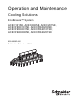
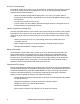
Operation and Maintenance Cooling Solutions EcoBreeze™ System ACEC101SE, ACEC200SE, ACEC201SE, ACECFR20101SE, ACECFR20200SE, ACECFR20201SE, ACECFR40101SE, ACECFR40200SE, ACECFR40201SE 990-3999D-001 Publication Date: June 2014 COIL ACCESS SUPPLY BLOWER ACCESS COIL ACCESS SUPPLY BLOWER ACCESS COIL ACCESS SUPPLY BLOWER ACCESS COIL ACCESS SUPPLY BLOWER ACCESS
Schneider Electric IT Corporation Legal Disclaimer The information presented in this manual is not warranted by the Schneider Electric IT Corporation to be authoritative, error free, or complete. This publication is not meant to be a substitute for a detailed operational and site specific development plan.
Contents Safety............................................................................................. 1 Important Safety Information . . . . . . . . . . . . . . . . . . . . . . . . . . . . . . . . . . .1 General Information................................................................... 2 Overview . . . . . . . . . . . . . . . . . . . . . . . . . . . . . . . . . . . . . . . . . . . . . . . . . . . .2 Frame . . . . . . . . . . . . . . . . . . . . . . . . . . . . . . . . . . . . . . . . . . . . . .
Operation.................................................................................... 12 Controllers . . . . . . . . . . . . . . . . . . . . . . . . . . . . . . . . . . . . . . . . . . . . . . . . .12 Controller redundancy . . . . . . . . . . . . . . . . . . . . . . . . . . . . . . . . . . . . . . 12 Module controllers . . . . . . . . . . . . . . . . . . . . . . . . . . . . . . . . . . . . . . . . . 12 Display Interface . . . . . . . . . . . . . . . . . . . . . . . . . . . . . . . . . . . . . . . .
Respond to Alarms. . . . . . . . . . . . . . . . . . . . . . . . . . . . . . . . . . . . . . . . . . 36 View alarms . . . . . . . . . . . . . . . . . . . . . . . . . . . . . . . . . . . . . . . . . . . . . . . 36 Clear alarms . . . . . . . . . . . . . . . . . . . . . . . . . . . . . . . . . . . . . . . . . . . . . . . 36 Frame alarms . . . . . . . . . . . . . . . . . . . . . . . . . . . . . . . . . . . . . . . . . . . . . . 36 Module alarms . . . . . . . . . . . . . . . . . . . . . . . . . . . . . . . . . .
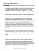
Safety Important Safety Information Read the instructions carefully to become familiar with the equipment before trying to install, operate, service, or maintain it. The following special messages may appear throughout this manual or on the equipment to warn of potential hazards or to call attention to information that clarifies or simplifies a procedure.
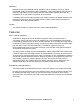
General Information Overview The EcoBreeze™ is a modular indirect evaporative and air-to-air heat exchanger cooling solution. The EcoBreeze has the ability to switch automatically between air-to-air and indirect evaporative heat exchange to consistently provide cooling to data centers in the most efficient way.
Module(s) Modules are fully self-contained cooling apparatus, with the exception of common Frame based water system for support of indirect evaporative cooling. Each Module has a degree of autonomy supported by its own integral controller. Each Module regulates the supply air temperature for its own outdoor air (OA) fan and compressor.
Air-to-air heat exchange The Module outdoor fan is used to move the ambient air, used as the cooling medium, across the air-to-air heat exchanger and condenser coil. The fan is controlled through a Modbus interface with the Module controller. • When the ambient air temperature drops below 4.4°C (40°F), the system water is dumped to prevent freezing or dumped after 24 hours (user adjustable setting) of spray free operation. • Only fans are required to move the air.
Basic system operation using HACS and a raised floor • Hot air from the servers is controlled through Hot Aisle Containment Systems (HACS). • The hot air rises to the ceiling plenum and feeds into the return ducting of the EcoBreeze. • The IT air is then cooled and returned to the data center through a raised floor plenum or cold aisle diffusers if a raised floor is not used.
Configuration Modules The EcoBreeze is comprised of up to eight identical Modules contained in a common Frame. These Modules are fully self-contained cooling apparatus, with the exception of a common Frame-based water system for support of indirect evaporative cooling (IEC). Each Module has a degree of autonomy supported by its own integral controller. Coordination of the Modules is handled by the master controller located in the Frame. Frame Each 12-meter (40-ft) Frame can accommodate up to eight Modules.
Commissioning DANGER HAZARD OF ELECTRIC SHOCK, EXPLOSION, OR ARC FLASH Turn off all power supplying this equipment before working on the equipment. All electrical work must be performed by licensed electricians. Practice Lockout/Tagout procedures. Do not wear jewelry when working with electrical equipment. Failure to follow these instructions will result in death or serious injury. WARNING HAZARD TO EQUIPMENT OR PERSONNEL All work must be performed by Schneider Electric authorized personnel.
Inspection Checklists Initial inspection The initial inspection ensures that the equipment has been properly installed, the location of the cooling unit has been properly prepared and the cooling unit is free of damage. DANGER HAZARD OF ELECTRIC SHOCK. To avoid possible personal injury or death, the access door locking mechanism must be re-engaged after access to a compartment for inspection or service requirements. Failure to follow these instructions will result in death or serious injury.
Electrical inspection checklist The electrical inspection verifies that all electrical connections are secure and correct and that the equipment is properly grounded. CAUTION ELECTRICAL HAZARD • All electrical wiring must comply with local and national codes and regulations. • The equipment must be grounded (do not use a water-pipe ground). Failure to follow these instructions can result in injury or equipment damage.
Mechanical inspection The mechanical inspection verifies that all mechanical components and connections are secure. NOTICE PIPING INSTALLATION Failure to properly install piping may result in improper cooling unit operation. Failure to follow these instructions can result in equipment damage. Ensure that the: 10 Mechanical connections are tight. Fans are turning freely and the blades are not distorted or bent. Pipe fittings are tight.
User interface inspection checklist The user interface inspection verifies that the sensors and internal communication links are installed properly. Ensure that: The CAN is connected to each Module and the bus is terminated at each end. Building management system is connected correctly and a terminator is wired into the final unit. Configure the settings for remote interface panel and input/output contacts.
Operation Controllers Controller redundancy The Frame system uses dual master controllers: a main Module and a redundant Module. The controllers are identical and monitor all Modules and external user interfaces. Only the acting master sends execution commands to Modules. The main controller sends the redundant controller a message periodically indicating its health.
Using the Display Interface There are two primary user interfaces: a graphical user interface (GUI) and the Modbus interface. The GUI is the human-to-machine interface and is the local interface to the system. The Modbus interface is the machine-to-machine interface and is the remote interface to the system. Scrolling status screens The display interface scrolls automatically and continuously through the following screens of status information.
Menu screens On any status screen press the > or < arrow to open the top level menu screen. If the display interface is inactive for a period of time, it will return to the scrolling status screens. Navigating the top level menu list Press the DOWN key (on the bottom of the display panel) to move the highlight bar down the list of menu options or select the item from the list by pressing the item name with your finger.
Navigating sub menus Operate View Frame Status View Module Status View Alarms Clear Alarms View Event Log Clear Event Log Esc You select the main menu item by pressing the ENTER key. The screen that opens is a sub menu item. In the illustration, the Set Date & Time menu item was selected. On the sub menu page, the changes can be made.
Start the System Path: Main > Operate > On/Off To start the System from the scrolling status screen, press the RIGHT key, select the Operate option on the list and press the ENTER key. NOTE: If the Operate Access password is non-zero, the password screen will be presented after ENTER is pressed. The screen changes to show Operate Off. Press ENTER to select Off. The highlighted box around the word Off will start to flash. Press the UP key to change the setting to On. Press ENTER to confirm the change.
About EcoBreeze Path: Main > About EcoBreeze This is a “view only” screen. No password is required. The screen displays the versions and revision levels of the firmware used in the Frame and Module controllers. • About Frame – HW Mask 481 v6.2 – MIM App Rev 1.X.X – RIM App Rev 1.X.X • About Modules > Module # – Select the Module from the list: The highlight bar will be located on the >> in the Select column. Press the UP or DOWN keys or press >> on the screen to select the Module you wish to view.
The Embedded Display Menus Some settings are only available by accessing the embedded display for the interface. Confine any changes to configuration and time out delays. Do not make other changes to the embedded menus. The network status screen To open the network status screen, press and hold the ENTER and LEFT keys for about three seconds. The password screen will open. The default password is -12. Press ENTER to cause the highlighted box to flash, then press the DOWN key.
Main menu Press >> at the top of the far right column (Address Status Mode) of the screen to display the main menu of the item you wish to view. Select Parameters to change: • Beep Mode: Produces a beep when a button is pressed. – 0 = No Beep 99 1 0 0 0 0 0 address status more OK >> >> >> >> >> >> >> Esc na3686a Network Status local node 1 node 2 node 3 node 4 node 5 node 6 – 1 - 2 = Loudness • Password Timeout: 0 - 240 seconds (the default is 60).
Configure the Frame The Frame distributes power from the mains to the Modules and its master controllers collect all sensor information. The Frame also supplies the water to and from the Modules. The water system is used to wet the outer surface of the indirect evaporative cooling (IEC) heat exchangers.
Active Flow Controller (AFC) status will be visible inside a highlighted box when the screen opens. Press ENTER to open the AFC screen.
Run Hours: • Pump A: - 0 Hrs • Pump B: - 0 Hrs • Water Treatment: - 0 Hrs • Module 1 Compressor • Module 2 Compressor • Module 3 Compressor • Module 4 Compressor • Module 5 Compressor • Module 6 Compressor • Module 7 Compressor • Module 8 Compressor • IT Fan 1 (each Module) • IT Fan 2 (each Module) • OA fan (each Module) • Reset Run Hours Reset Run Hours can be accessed from this screen and will be in the highlighted box when the screen opens. To Reset Run Hours. Press ENTER. The password screen opens.
Reset (Option) Run Hours Enter Yes to confirm ESC to exit Yes/No No will be in the highlighted box on the screen. Press ENTER to cause the box to flash. Then press the UP key to change the No to Yes. Press ENTER to save your change. Press ESC to return to the option selection screen. Path: Main > Configure Frame Air Controls. (Requires device password) • Setpoints – Supply Air: 20°C - 32.2°C (68 - 90°F) – Containment: 100.0 Pa (0.4” WC) • Fan Speed: 20% - The speed of the IT fans.
Water Controls. (Requires device password) • Lead Pump: A or B • Pri Water Src: A or B • Drain Basin: Basin Draining - When this menu item is selected, if the Frame is off (Operate = Off), the basin will be drained. Use the UP or DOWN keys to move the highlight box to your selection and press ENTER to select it. The box will start to flash. Use the UP or DOWN arrows to change the setting. Press ENTER to save the setting. If you select Drain Basin, when ENTER is pressed, the confirmation screen opens.
• DP Sensor Sel: – None: No differential pressure (DP) measurements are to be supplied to the unit. – 4-20 mA, 0-10 VDC: A user supplied DP sensor of the selected type has been connected to the remote interface panel. – BMS: DP measurements are to be input via the Modbus interface. – AFC: DP measurements are to be controlled by the AFC. • DP Filter Coef: 0.0 - 1.0 - This parameter is a filtering coefficient for the DP sensor.
Water Service. (Requires admin password) • Setpoint: 500 - 15000 uS/cm • Deadband: 25 - 15000 uS/cm • Conductivity Min/Max: Select the range that corresponds to the selection made on the conductivity sensor. – 500 - 2500 uS/cm – 2500 - 15000 uS/cm • ServiceCmplt: No/Yes - Select Yes to clear the Water Treatment System Maintenance Required alarm and to set the Last Service date to the current date. • Last Service: 01/01/2001- Displays the last time the water treatment system was serviced.
ActiveFlowCtrl Setup. Configure AFC settings.
View Setup. Press the UP or DOWN keys to view all sensor information being collected by the Frame controllers. No password is required to view this screen. • • • • • • • • • • • • • • • • • • • • • • • • • • • • 28 Supply Air Setpt: 75.0°F/°C Contain Setpt: 100.0 Pa Fan Speed: 0% Conduct Setpt: 2500 uS/cm Conduct Dedbnd: 1000uS/cm Lead Pump: A Pri (Primary) Water Src: A IT Fan Mode: Auto Elevation: ftx10/mx10 Damper Present: No Contain Gain: 0.000%/Pa Contain Reset: 0.
Building management system (BMS) The Modbus interface allows the EcoBreeze to communicate with a BMS. The Modbus connection is available in two locations on the Modbus hub of the Frame controller: • RJ-45 In port • 3-wire on terminal block WIRING CONTACTS FOR 3-WIRE CONNECTION RJ-45 IN PORT DDC PANEL ENCLOSURE 1MOD na3660a D(B) D(A) 1MOD 0V See the EcoBreeze Frame Installation Manual for more information. Configure Modbus.
Module Configuration The Module configuration settings define which components are available and how the Module should operate. Up to eight Modules can be housed in a common Frame. The Modules are fully self contained with the exception of the common Frame-based water system to support the indirect evaporative cooling. Each Module has its own controller. The controllers in the Modules are coordinated by the Frame active master controller.
DX components • Discharge Pres.: psi/kPa - The pressure at the discharge port of the compressor. • Discharge Temp.: °F/°C - The temperature of the refrigerant at the discharge port of the compressor. • Suction Pressure: psi/kPa - The pressure at the suction port of the compressor. • Suction Temp.: °F/°C - The temperature of the refrigerant at the suction port of the compressor. • Compressor Power: kW - The rate of energy consumed by the compressor.
View Setup. This is a read-only view of the above configurations. No password is required. • Module # - Available - Yes/No – Press the UP or DOWN keys to move the highlighted box to the Module # you want to select, then press ENTER. Operate - On/Off The display screen only shows if the Module is Off or On. Select Prev... in the lower-left corner of the screen to return to the previous screen. From there, select the next Module in the list to view.
Environment Control The EcoBreeze can sense ambient temperature and automatically switch between DRY and WET mode to optimize efficiency. The Frame controls the Modules to provide the conditioned air to the computer room. Air-to-air heat exchange Air-to-air heat exchange is the DRY mode and only requires the power of the fans to move the air (extremely energy efficient).
The setpoint for each mode must be within the following ranges: • Supply Air - 75.0°F (See “Air Controls” on page 23.) • Containment - 100.0 Pa (See “Air Controls” on page 23.) Configure thresholds A threshold is used to trigger an alarm. For example, if you want to be notified when the supply air temperature exceeds 32°C (90°F), then set the supply temperature high threshold to 90°F. The controller will generate an alarm when the supply air temperature exceeds the threshold.
Event Log The event log saves status information and a message each time a change in the system is detected. Alarms and events are recorded in the log. View log Path: Main > View Event Log The Event Log Screen contains • The event index number in the log, and the device (Frame/Module) to which it applies. • The severity level of the alarm is also listed (Warning/Critical). • The time and date the event occurred. • The name and description of the event. To view the next event in the log, navigate to Prev..
Respond to Alarms When an alarm is triggered, the display alerts you through the following methods: • The screen will flash Active Alarm(s) on the bottom of the main screen. • Alarm and event logs View alarms Path: Main > View Alarms To view the next alarm, navigate to Next..., then press ENTER. Another method of navigating the alarm list is to press the word First at the bottom of the screen to go to the first entry or Next... to go to the next entry in the alarm list.
AFC ModBus Communication Error Critical Insufficient Airflow Warning Data Center Airflow Control Warning Differential Pressure High/Low • Check ModBus cable between AFC master sensor and EcoBreeze frame controller. • Power or Sensor failure of AFC master sensor. • For assistance, contact Schneider Electric Customer Support. • Ensure plenums are clear of obstructions. • Ensure air ports on AFC are clear of obstructions. • Ensure sufficient cooling capacity exists for the load.
Primary Water Supply Loss Critical Secondary Water Supply Loss Critical Water Pump A/B Fault Critical Basin Water Level High Warning Basin Water Level Low Critical Water Treatment System Error Warning Water Level Sensor Fault, MIM Critical (Frame master controller) Water Level Sensor Fault, RIM Critical (Frame redundant controller) Unable To Drain Basin Critical Air Pump 1 Fault Critical Air Pump 2 Fault Critical Loss of Water Management Power Circuit Critical • Check the wiring, verify
Ambient Temperature Sensor Fault, RIM (Frame redundant controller) Critical Ambient Humidity Sensor Fault, Warning MIM (Frame master controller) Ambient Humidity Sensor Fault, Warning RIM (Frame redundant controller) High Return Temperature Warning Low Return Temperature Warning High Supply Temperature Warning Low Supply Temperature Warning • Check the wiring. • Check and clean the sensor. • Check the sensor calibration. • Replace the sensor if needed. • Check the wiring.
Module alarms • “COMPRESSOR ALARMS” on page 40 • “ELECTRONIC EXPANSION VALVE (EEV) ALARMS” on page 40 • “FAN ALARMS” on page 41 • “POWER ALARMS” on page 41 • “REFRIGERATION SYSTEM ALARMS” on page 41 • “TEMPERATURE/HUMIDITY ALARMS” on page 42 • “WATER SYSTEM ALARMS” on page 43 • “VARIABLE FREQUENCY DRIVE (VFD) ALARMS” on page 43 Name Severity Alarm Actions COMPRESSOR ALARMS Compressor Start Failed Critical Compressor Overcurrent Fault Critical Compressor Impending Shortcircuit Fault Compressor Short to
EEV Temperature Sensor Fault Critical EEV Motor Fault Critical EEV Communication Fault Critical • Check the suction pressure transducer reading. • Check the suction temperature sensor reading. • Check operation of the EEV. • Replace the sensor. • Check operation of the EEV. • Check the wiring and connections. • Replace the valve or motor if necessary. Check the communications cabling and power to the device.
Discharge Temperature Sensor Warning Fault Refrig Liquid Temperature Sensor Fault Warning Condenser Coil De-Ice Active Warning Filter Access Door Open Warning Warning Filter Access Door Open Alarm Critical High Head Pressure Critical Low Suction Pressure Warning Low Suction Pressure Lockout Critical Cap Fault or Motor Overload or Critical Overspeed • Check the wiring. • Check and clean the sensor. • Check the sensor calibration. • Replace the sensor. • Check the wiring.
Supply Temperature Sensor Fault Critical • Check the wiring. • Check and clean the sensor. • Check the sensor calibration. • Replace the sensor. WATER SYSTEM ALARMS IEC Temperature Sensor Fault Warning IEC Performance Degradation Warning Loss of IEC Spray Water Critical Dirty Filter Warning • Check the wiring. • Check and clean the sensor. • Check the sensor calibration. • Replace the sensor. • Check the strainers for obstruction. • Check the outdoor air openings for obstructions.
Troubleshooting NOTE: The EcoBreeze operates using controllers to control internal functions along with variable frequency drives (VFDs). If either detects a problem, it will go into an alarm mode. Refer to the remote display panel active alarms and status screens for additional help. Problem Possible Cause Corrective Action Module # will not run • No power • Check that the disconnect switch on the Module control panel has not been shut off. • Check Module address configuration.
Problem Possible Cause Corrective Action Module powered but will not operate • System is off • Remote shutdown or input contact is active • System is in alarm • Turn the System on. • Check input contact configuration settings. • Dirty or blocked evaporator coil • Low refrigerant charge • Clean evaporator coil. • Check for proper subcooling. Repair leak and recharge the system. • Check for excessive pressure drop. Replace the filter drier if necessary. • Check expansion valve operation.
Maintenance General Task Descriptions Fans WARNING UNINTENDED EQUIPMENT OPERATION Turn off the system, disconnect all power sources, and Lockout before performing work on the fans. Failure to follow these instructions can result in serious injury or equipment damage. • Verify that the fan hardware is tight. • Verify that electrical connection is secure. Filters Clean/replace air filters. Regular filter maintenance is vital to proper unit operation.
Inspecting the Heat Exchangers. Inspect heat exchangers Module by Module. Remove power from the Module to be inspected. Be certain that the branch circuit feeding the Module is turned off. Open the access panels. Remove one section of mist eliminators from the upper portion of the Module. Inspect the top of the heat exchangers for buildup of mineral deposits, dirt, or microbial contamination.
General cleaning Inspect and clean the EcoBreeze system on a regular basis. Do not use cleaners, chemicals, or other materials with strong fumes or odors. Thoroughly remove all cleaning solution residue from interior surfaces. • Remove any debris. • Exterior: Spray wash the exterior with low pressure water and a mild detergent. All detergent must be removed with clean water.
Monthly Preventive Maintenance Prepared By: _________________________________ Model Number: _______________________________ Serial Number: _______________________________ Date: ______________________________________ Mechanical Verify that the water treatment specialist has made the monthly site visit (when applicable). NOTE: Some regions do not require monthly checks of the water treatment system. • Conductivity settings are in proper range. • Fill, drain, and blow down functions are operating properly.
Quarterly Preventive Maintenance * Perform all the Monthly Preventive Maintenance items and the items below. Prepared By: _________________________________ Model Number: _______________________________ Serial Number: _______________________________ Date: ______________________________________ Mechanical Check the condition of the trough and basin water level sensors. Check and record the outdoor air temperature and humidity sensor readings.
Semi-Annual Preventive Maintenance * Perform all the Monthly and Quarterly Preventive Maintenance items and the items below. Prepared By: _________________________________ Model Number: _______________________________ Serial Number: _______________________________ Date: _______________________________________ Cleanliness Check the cleanliness of the evaporator coil. Clean if required. Check condenser coil, remove debris; check top surfaces of the IEC.
Worldwide Customer Support Customer support is available at no charge via e-mail or telephone. Contact information is available at www.apc.com/support/contact. © Schneider Electric is owned by Schneider Electric Industries S.A.S., or its affiliated companies. All other trademarks are property of their respective owners.