
Instruction manual


Instruction manualREVAMP2600
13
impedance applications. The input signal from channel 1 is used
for both channels.
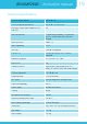
8. CH1 full range linked CH2 TRAFO (led 3 + led 4): channel 1
is optimized for low impedance full range loads, channel 2 is
optimized for low transformer loads (100 volt applications). The
input signal from channel 1 is used for both channels.
9. CH1 TRAFO linked CH2 TRAFO (led 2 + led 3 + led 4): channel 1
and 2 are optimized for transformer loads. The input signal from
channel 1 is used for both channels.
10. CH1 SUB linked CH2 TRAFO TOP (led 1 + led 3 + led 4):
frequencies below 100 Hz are sent to the sub channel (CH1).
Frequencies above 100 Hz are sent to the top channel (CH2).
Filter slope is fixed: 12 dB/oct or second order Butterworth
characteristic. The input signal from channel 1 is used for both
channels.