
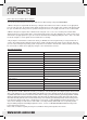
Specifications

INFO@APART-AUDIO.COM
3
18
19 20
17
21
22
23
24
25
26
27
28 29 30 31 32 33
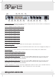
17. Ground connector. Connect your system’s ground or safety ground on this connector if this is not already done
by mounting the unit in a properly grounded rack.
18. Line 1 right input on balanced XLR connector.
19. Line 1 left input on balanced XLR connector.
20. Line 2 L/R cinch or RCA connector.
21. Line 3 L/R cinch or RCA connector.
22. Line 4 L/R cinch or RCA connector.
23. Line 5 L/R cinch or RCA connector.
24. Line 6 L/R cinch or RCA connector.
25. Line 6 L/R cinch or RCA connector.
26. Mono/stereo switch. Pressing this switch, the stereo line inputs 1 to 6 are mixed to mono.
27. Ext. mute switch connector. Connect your external mute switch on this connector, do not apply any voltages on
this connector !!!
28. Vox mute level. Use this controller to set the level where the ‘vox’ mute circuitry of mic 1 will be active.
29. Zone 2 right output on balanced XLR connector.
30. Zone 2 left output on balanced XLR connector.
31. Mic 2 XLR/ TRS jack combo input. This is a copy of the front MIC 2 TRS input jack. You can use the front or
rear input, but not simultaneously. You can apply phantom power to the mic by closing jumper JP1 inside the
PM7400 MKII. Only a qualied technician can do this !
32. Mic 1 XLR/ TRS jack combo input. This is a copy of the front MIC 1 TRS input jack. You can use the front or
rear input, but not simultaneously. You can apply phantom power to the mic by closing jumper JP2 inside the
PM7400 MKII. Only a qualied technician can do this !
33. Mains inlet/mains fuse connector. Connect the supplied mains cable here. There is also a 315 mAT mains fuse
inside this connector. In case the fuse blows, replace it only with a fuse of the same rating.