
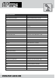
Specifications

INFO@APART-AUDIO.COM
7
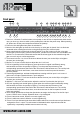
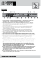
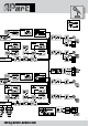
14. Mic mix output: this unbalanced cinch connector contains the mic mix signal from mic/line
inputs 1 to 5 and is meant to be connected to another PM1122 in a chain.
15. Link input: this unbalanced cinch connector accepts the signal from another PM1122 in a
chain. You could also use it as a mono unbalanced line 5 input. The level from this input is
adjusted with the front mic/line 5 + link knob.
16. Mic 1 to 5 phantom switch: ip down the dipswitch from channel 1 to 5 if you want to apply
a 20 VDC phantom power to input 1 to 5. Don’t use unbalanced sources in combination with
phantom power turned on on the same channel !
17. Mic/line 1 to 5 sensitivity knobs: turn these knobs to adjust mic/line 1 to 5 input sensitivity and
gain: the signal/clip led present on mic/line input 1 to 5 is your guide: turn down the knob to
the left rst, and gradually turn it to the right while you are speaking loudly in the mic or while
the line signal is applied. When the signal/clip led turns red, you are overloading the input.
Turn the knob to the left a little until the led doesn’t light up red anymore. Take your time to
preset all mic/line inputs this way.
18. Input 3 to 5 input blocks: connect your balanced mic or line signals on these euroblock
connectors.
19. Input 1 and 2 input blocks: connect your balanced mic or line signals on these euroblock
connectors. Additionally connect the mic 1 and/or mic 2 switch(es) on these blocks to activate
the chime and priority. These contacts can be used for inputs 3-5 as well.
Please note the priority system; the MIC1 contact will mute MIC2-3-4-5 + Music, and the
MIC2 contact will mute Music (if dipswitch 4 is set)
20. Ground connector: connect your system’s ground or safety ground on this connector if this is
not already done by mounting the unit in a properly grounded rack.
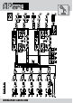
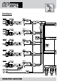
For additional functionality, there are also 2 open collector outputs at the rear controlled by the
priority switch, one output per zone. They can only be used by qualied technicians. Maximum
sinkable current per output is 50 mA, maximum voltage is 24VDC. No AC voltages are allowed
on these outputs ! In case of inductive loads such as relays, provide additional measures to avoid
damage to the open collector outputs.
Please use the schematic shown below as a guideline: