
Specifications

INFO@APART-AUDIO.COM
5
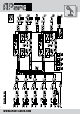
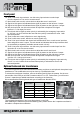
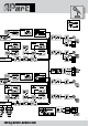
Front panel
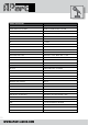
Optional balanced mic transformers
16. Zone 1 line/music input selector: turn this rotary input selector to select input
from line inputs A to D or set it to remote control.
17. Music level knob: turn this volume knob to adjust the zone 1 music level.
18. Signal led: this green led indicates that a signal is present on the left zone 1 output.
19. Signal led: this green led indicates that a signal is present on the right zone 1 output.
20. Mic mix level knob: turn this volume knob to adjust the microphone mix signal
(mic/line 1-5 + link input) for zone 1.
21. Priority led: this led lights up when priority is activated by the emergency input and/or
by the mic 1 or mic 2 switch at the rear and when priority is activated for zone 1 with
the rear dipswitch.
22. Zone 2 bass tone control, effective on music signals only.
23. Zone 2 treble tone control, effective on music signals only.
24. Zone 2 line input indicator leds: these leds indicate which line or music source input has
been assigned to zone 2 output. The red remote led indicates that the input selector shall
be operated by a separately available remote control unit only.
25. Zone 2 line/music input selector: turn this rotary input selector to select input from line
inputs A to D or set it to remote control.
26. Music level knob: turn this volume knob to adjust the zone 2 music level.
27. Signal led: this green led indicates that a signal is present on the left zone 2 output.
28. Signal led: this green led indicates that a signal is present on the right zone 2 output.
29. Mic mix level knob: turn this volume knob to adjust the microphone mix signal
(mic/line 1-5 + link input) for zone 2.
30. Priority led: this led lights up when priority is activated by the emergency input and/or by
the mic 1 or mic 2 switch at the rear and when priority is activated for zone 2 with
the rear dipswitch.
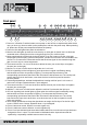
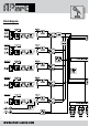
The PM1122 printed circuit board has all the necessary provisions to add optional microphone input
transformers. This modication can only be done by a qualied technician.
To access the transformer locations, remove the bottom and lid from the preamp. On the com-
ponent side of the PCB you will nd 5 locations called IT1 to IT5. Furthermore, you will have to
remove 2 capacitors per added transformer according to the list below.
We recommend the following brand and type of transformer: Neutrik NTM 1.
The suggested transformer’s pin layout ts perfectly on the PCB
After soldering the transformer from the soldering side, please remove the 2 capacitors as listed in
the table to complete the modication.
Microphone
input nuMber
pcb location capacitor to
reMove
Mic1 it1 c13 & c14
Mic2 it2 c213 & c215
Mic3 it3 c44 & c45
Mic4 it4 c57 & c58
Mic5 it5 c85 & c86