
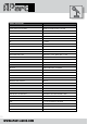
Specifications
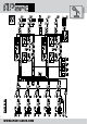

WWW.APART-AUDIO.COM
4
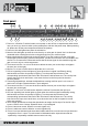
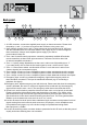
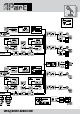
1. Power on / off switch. Push the button to turn power on and off. As an experienced audio device
user, you know you have to switch on the preamp rst, and then the power amp. When powering
off, please turn off the power amps rst and then the preamp.
2. Power led: this led lights when power is switched on.
3. Mute led: this led lights up when the mute circuitry or noise gate is closed. Use it to eliminate
unwanted noise or background noise coming through from your mic/line inputs.
4. Noise gate threshold: set the knob to the off position if you don’t want to use the noise gate.
Set the gate so that it opens (mute led dark) when you talk into one of the mics connected to the
mic/line 1 to 5 connectors. Please take notice that the chime signal is also routed through this
gate, so use it only as a noise suppressor.
5. Tone control mic/line 1 to 4: turn the knob to darken the tone (turn to the left) or to brighten
the tone (turn to the right).
6. Mic/line 1 to 4 level: use this knob to adjust the mic 1 to 4 level.
7. S/C led: signal/clip led: the led lights up green when the mic signal is sufciently strong,
and becomes red if the mic preamp is clipping. Turn the preset input trimmer of the
corresponding input down at the back of the unit when the led becomes red. The red clip leds
monitor the input circuit at all times, even when the level on the front panel is turned to
the zero position.
8. Zone assign dipswitches: activate the dipswitches to assign mic/line input 1 to 4 to zone 1
and/or zone 2 output. Dipswitch down = input assigned.
9. Tone control mic/line 5 + link: turn the knob to darken the tone (turn to the left) or to brighten
the tone (turn to the right).
10.Mic/line 5 + link level: use this knob to adjust the mic/line 5 level and/or the link input.
11.S/C led: signal/clip led: the led lights up green when the mic/line signal is sufciently strong,
and becomes red if the mic preamp is clipping. Turn the preset input trimmer of the
corresponding input down at the back of the unit when the led becomes red. The red clip
leds monitor the input circuit at all times, even when the level on the front panel is turned
to the zero position.
12.Zone assign dipswitches: activate the dipswitches to assign mic/line input 5 or the link input
to zone 1 and/or zone 2 output. Dipswitch down = input assigned.
13. Zone 1 bass tone control, effective on music signals only.
14. Zone 1 treble tone control, effective on music signals only.
15. Zone 1 line input indicator leds: these leds indicate which line or music source input has been
assigned to zone 1 output. The red remote led indicates that the input selector shall be
operated by a separately available remote control unit only.
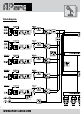
Front panel
8 125 94
2314 2213 12718 2819 2516
2617 29 3020 21 22415
6 107 113