MANUAL PM1122 INFO@APART-AUDIO.
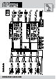
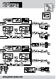
Blockdiagram 2 WWW.APART-AUDIO.
Introduction After reading these pages, most of you will be able to connect sources and operate this unique preamp/mixer without further instructions. For more details, please take a look at the blockdiagram for better understanding and refer to the front and rear panel layout descriptions on the next pages. The PM1122 features 5 mono mic/line balanced inputs with individual sensitivity, level and tone adjustment potmeters. Each mic input has its own phantom dipswitch at the back.
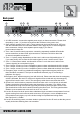
Front panel 4 3 5 8 6 7 9 12 15 17 20 21 24 26 29 30 2 10 11 13 14 16 18 19 22 23 25 27 28 1 1. Power on / off switch. Push the button to turn power on and off. As an experienced audio device user, you know you have to switch on the preamp first, and then the power amp. When powering off, please turn off the power amps first and then the preamp. 2. Power led: this led lights when power is switched on. 3. Mute led: this led lights up when the mute circuitry or noise gate is closed.
Front panel 16. Zone 1 line/music input selector: turn this rotary input selector to select input from line inputs A to D or set it to remote control. 17. Music level knob: turn this volume knob to adjust the zone 1 music level. 18. Signal led: this green led indicates that a signal is present on the left zone 1 output. 19. Signal led: this green led indicates that a signal is present on the right zone 1 output. 20.
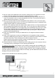
Back panel 1 6 2 3 4 5 7 8 14 9 10 11 12 13 15 16 17 18 19 1. 24 VDC connector: connect the supplied power supply on these connectors. Please mind the polarity (+ and - ) if you have to reconnect the connector to the power cord. 2. Open collector outputs zone 1 and 2: These outputs can sink max 50mA at 24 VDC max. See the schematic below for connection details. Don’t apply any AC or mains voltages to these connectors.
14. Mic mix output: this unbalanced cinch connector contains the mic mix signal from mic/line inputs 1 to 5 and is meant to be connected to another PM1122 in a chain. 15. Link input: this unbalanced cinch connector accepts the signal from another PM1122 in a chain. You could also use it as a mono unbalanced line 5 input. The level from this input is adjusted with the front mic/line 5 + link knob. 16.
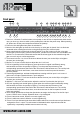
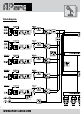
Blockdiagram 8 WWW.APART-AUDIO.
INFO@APART-AUDIO.
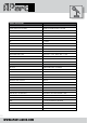
Technical specifications Outputs Output stereo zone 1 balanced euroblock connector 6dB, 2V, 100 ohm Output stereo zone 1 unbalanced cinch connector 0dB, 1 V, 100 ohm Output stereo zone 2 unbalanced cinch connector 0dB, 1 V, 100 ohm Frequency response 20Hz - 22 KHz Noise > 93 dB THD < 0,008 % Crosstalk > 70 dB Max nominal gain +6 dB Max output voltage +19 dBV, 9 V Insert pcb for signal-processing pcb ready, processors optional Tone control zone 1 and 2 bass 75Hz +/-10 dB treble 10KHz +/-
Technical specifications Tone control mic/line 1 to 5 from 100Hz/+3dB,10kHz/-6dB to 100Hz/- 9dB, 10KHz/+4dB Link input 20 kohm -2,5 dB 770mV Link output 100 ohm -2,5 dB 770mV Noise gate threshold mic/line 1 to 5 off to -20 dB General Power supply (adapter included) 24 VDC 1000 mA / max 24VA Dimensions (WXDxH) 438 X 222 (245 with knobs & connectors) X 44mm Shipping weight 4.0Kg Net weight 3.
Options •pm1122RL •pm1122int Analog remote control with local audio input. 2-zone digital remote interface. •pm1122R Analog remote control. •pm1122R Plug-in receiver module for RF wireless remote control. Ultra flat wireless control. •pm1122WSLV •pm1122WW PC software included with the PM1122INT interface. ANY SUGGESTION? They are well appreciated and eventually rewarded! Send your ideas or suggestions to suggestions@apart-audio.