
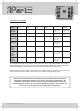
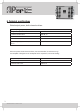
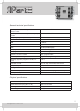
Specifications

INFO@APART-AUDIO.COM
11
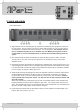
10)RightbalancedinputonXLRconnector,thisconnectoriswiredinparalleltoconnector‘9’.
Thisallowsyoutolinkthebalancedsignaltoanotheramplier.
11) APCrightchannelon/offswitch:always leave this switched on.
Warning: turning off the APC circuit will also bypass the amplier’s output stage
temperature protection. This is for service purposes only.
12)APCpowercontrolrightchannel:turntheAPCcontroltoachievethedesiredprogramoutput
power.Theindicatedpowerlevelisinreferencetoa4ohmsspeakerload.Thiscanalsobe
usedforenvironmentalnoiselimiterpurposes.TheAPCcircuitrywillreducetheinputstage
gain to guarantee the preset program power output with musical dynamics.
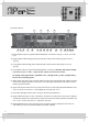
13)Tube/solidsoundselector:setthisswitchtothetubesettingforauthentictubelikesound,or
tosolidfornormalapplications.Thedifferencesareverysubtleandwillonlybenoticeableon
very high quality speaker systems ! Set this one to solid for normal applications.
14)APCpowercontrolleftchannel:turntheAPCcontroltoachievethedesiredprogramoutput
power.Theindicatedpowerlevelisinreferencetoa4ohmsspeakerload.Thiscanalsobe
usedforenvironmentalnoiselimiterpurposes.TheAPCcircuitrywillreducetheinputstage
gain to guarantee the preset program power output with musical dynamics.
15)APCleftchannelon/offswitch:always leave this switched on.
Warning: turning off the APC circuit will also bypass the amplier’s output stage
temperature protection. This is for service purposes only.
16)LeftbalancedinputonXLRconnector,thisconnectoriswiredinparalleltoconnector‘17’.
Thisallowsyoutolinkthebalancedsignaltoanotheramplier.
17)LeftbalancedinputonXLRconnector,thisconnectoriswiredinparalleltoconnector‘16’.
Thisallowsyoutolinkthebalancedsignaltoanotheramplier.
18)Leftunbalancedinputoncinchconnectors:usethetoporbottomcinchconnectortoapplyan
unbalancedsignalontheleftchannel.
Theseconnectorsarewiredinparallel,thismeansyou
can use the second connector as a signal link connector.
19) APCactiveledleftchannel,thisisacopyofthefrontpanelAPCled.
20)Leftchannelinputlevelcontrol:turnthelevelcontroltoalevelthatguaranteesdistortionfree
music under all circumstances, avoid clipping at the input at all costs !
21)Bridgemodeswitch:pushthisswitchtoconverttheamplierintoamonobridgeamplier.
In this case you can apply an input signal to the left channel only ! Leave the right channel
connectors open ! Bridge mode input level is controlled by the left channel level controller
(‘20’)only.Connectyourspeakertotherightchannel+(plus)connectorandtotheleft
channel+(plus)connector!Neverusethespeakeroutput–(minus)connectorsinbridge
mode!Theledabovethebridgemodeswitchwillindicatethattheamplierisinbridgemode.
Minimumbridgemodespeakerloadis8ohms.