
User Manual


12
● To let system save the desired sleep timer value into the memory,
simply let go of the adjustment knob and the system will automatically
save the value into CPU memory.
3. Turn on the Soldering Iron function switch to start using the Soldering
Iron.
4. The sleep timer will start counting down once the Soldering Iron
function switch is turned ON and no adjustments are made to Soldering
Iron set temperature.
5. When the timer expires, the Soldering Iron will shut down its heater and
display three dashes “- - - “. This indicates the Soldering Iron is in sleep
mode.
6. To wake the Soldering Iron simply adjust the temperature knob A3.
7. To disable the sleep timer simply set the sleep timer duration to 0.
8. Access and disable the sleep feature of the Soldering Iron:
● Turn Soldering Iron, SMD and Smoke Absorber function switch off.
● Press and hold the hot air temperature increase button A6.
● The Soldering Iron display A2 will turn to “t##” , indicating it is now on
sleep timer adjustment mode.
● Turn the Soldering Iron adjustment knob completely counter clockwise
to set timer to “t00”.
● let system save the desired sleep timer value into the memory.
SOLDERING IRON DIGITAL CALIBRATION
1. The Soldering Iron has a digital calibration feature that allows the
user to easily adjust the temperature offset of the Soldering Iron +
or—50 degrees.
2. Reset the calibration number of the Soldering Iron:
● Turn SMD and Smoke Absorber function switch off.
● Turn Soldering Iron function switch on.
● Press and hold the hot air temperature increase button A6.
OPERATING GUIDELINES
9
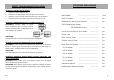
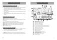
SMD REWORKING
1. Ensure All function switches (B1,B2,B3) are in off position.
2. With the unit plugged to the main power source, turn on the system by
switching the main power switch on. The panel should initially display
the product name in a scrolling manner and display OFF on panel C2
after.
NOTE:
The product name may scroll more than once upon plugging the
system to the power source. The system is trying to determine the appropriate
operating frequency based on the user location. See Basic Troubleshooting
Guide (page 14-15).
2. Turn ON the “SMD Rework” function switch, B3.
3. The system will start to blow hot air and increase the temperature to
90°C, by factory default setting. Display panel, C2, shows the user-
defined (set) temperature while display panel, C3, shows the actual
temperature of the system.
4. Adjust air pressure by turning knob A1. It is recommended to keep the
knob setting at 3 or above. It is also advised to adjust the airflow level
first before increasing the air temperature to avoid building of too much
heat on the Hot Air Gun thus burning the heating element.
NOTE:
If air pressure knob is set to minimum upon switching the SMD Rework ON,
the system will automatically run at average airflow to protect the device from
excessive heat. The user will gain full control once the knob has been adjusted to
the desired airflow level.
OPERATING GUIDELINES