LM-700 LM-700 17 inch TFT LCD Monitor User’s Manual by Envision Peripherals, Inc. www.aocmonitor.com Before operating your monitor, please read this manual thoroughly.
For Your Safety LM-700 FCC Statement Notice This equipment has been tested and found to comply with the limits for a Class B digital device, pursuant to Part 15 of the FCC Rules. These limits are designed to provide reasonable protection against harmful interference in a residential installation. This equipment generates, uses and can radiate radio frequency energy, and if not installed and used in accordance with the instructions, may cause harmful interference to radio communications.
Precautions • Do not use the monitor near water, e.g. near a bathtub, washbowl, kitchen sink, laundry tub, swimming pool or in a wet basement. • Do not place the monitor on an unstable cart, stand, or table. If the monitor falls, it can injure a person and cause serious damage to the appliance. Use only a cart or stand recommended by the manufacturer or sold with the monitor. If you mount the monitor on a wall or shelf, use a mounting kit approved by the manufacturer and follow the kit instructions.
For Your Safety LM-700 Special Notes on LCD Monitors General Notes The following symptoms are normal with an LCD monitor and do not indicate a problem: • Do not install the monitor near heat sources such as radiators or air ducts. • Due to the nature of the fluorescent light, the screen may flicker during initial use. Turn off the Power Switch and then turn it on again to make sure the flicker disappears.
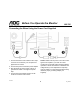
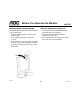
Before You Operate the Monitor LM-700 Installing & Removing the Base General Features: Package Contents • 17" (43.2cm) TFT Color LCD Monitor The box that your monitor was shipped in should have included the following items: • Crisp, Clear Display for Windows • Supports Resolutions up to 1280 X 1024 pixels @75Hz • EPA ENERGY STAR® • Ergonomic Design • Space Saving, Compact Case Design LM-700 1. 2. 3. 4. 5. 6.
Before You Operate the Monitor LM-700 Connecting the Wires Using the Power Cord Supplied 1. Connect the built-in video cable into the 15-pin connector on the back of your computer and tighten the two screws. 2. Connect the power cord into the power adaptor. 3. Plug the other end of the power cord into a grounded AC outlet or UL-approved power strip. 4. Connect the power adaptor into the DC IN socket on the back of the monitor.
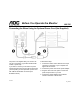
Before You Operate the Monitor LM-700 Connecting the Wires Using An Optional Power Cord (Not Supplied) The power cord supplied with your monitor can only be connected to a grounded electrical wall socket or power strip. If you wish to connect your monitor to a power supply using the power input socket on the back of your computer, you must purchase a power cord with CEE-22 terminated connectors (see illustration above). LM-700 Follow these steps: 1.
Before You Operate the Monitor LM-700 Preparing to Install An Optional Wall Mounting Arm (Not supplied) This monitor can be attached to a wall mounting arm you purchase separately. Disconnect power before this procedure. Follow these steps: 1. Pull the screw covers off the back of the monitor. 2. Support the base and remove the screws. 4. Remove the back cover from the panel. 5. Follow the manufacturer’s instructions to assemble the wall mounting arm. See next page for further installation instructions.
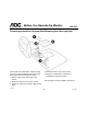
Before You Operate the Monitor LM-700 Install An Optional Wall Mounting Arm (Not supplied) Follow these steps to finish installing the wall mounting arm: AOC's Model LM700 is compatible with the Ergotron line of mounting and arm solutions. 1. Place the wall mounting arm onto the back of the monitor. Line up the holes of the arm with the holes in the back of the monitor. Contact Ergotron at 800-888-8458 or visit their web site at www.ergotron.
Before You Operate the Monitor LM-700 Adjusting the Viewing Angle How to Install INF & ICM File For optimal viewing, adjust the monitor's angle to your own preference. 1. Insert the Windows 95/98/2000/ME/XP INF Driver Disk into your floppy drive. • Hold the stand firmly when you change the monitor's angle. 2. Follow the Add New Hardware Wizard instructions on the screen. • You can adjust the monitor's angle from -5° to 30°. 3.
Operating Instructions LM-700 Front Panel Buttons Auto: Press this button to automatically set the H-Position, V-Position, Clock and Focus settings. Brightness: Press this button to adjust the picture’s brightness. If the OSD window is open, this button allows you to move within the window and select desired functions. Contrast: Press this button to adjust the picture’s contrast. If the OSD window is open, this button allows you to move within the window and select desired functions.
Operating Instructions LM-700 Adjusting the OSD Settings 1. Press the MENU button to open the OSD window. 2. Press the < or > buttons until the desired function is highlighted. 3. Press MENU to open the function’s window. 4. Press the < or > buttons to change the settings of the function. LM-700 5. To save and exit, highlight the EXIT icon and press MENU or leave the monitor alone for 10 seconds. If you want to adjust any other function, repeat steps 2-4.
Operating Instructions DOS-mode LM-700 pattern has vertical stripe noise, or the characters are twisted): This feature allows you to choose between resolutions of 720 x 400 or 640 x 400 while working in DOS-mode. Follow the instructions for selecting functions in the OSD window as listed on the previous page. Press your monitor’s Power button off and then on to activate your chosen DOS-mode resolution. Note: the default DOSmode resolution is 720x400@70Hz.
Technical Support (FAQ) Problem LM-700 Possible Solution Power LED is not ON • Make sure the power button is ON. • Make sure the power adaptor is properly connected to a grounded power outlet and to the monitor. No Plug & Play • Confirm that your computer is Plug & Play compatible. • Confirm that your video card is Plug & Play compatible. • Inspect the video cable and make sure that none of the pins are bent. • Make sure the AOC monitor drivers are installed.
Technical Support (FAQ) Problem LM-700 Possible Solution Screen image is not centered or sized properly • Adjust the CLOCK1 and FOCUS2 settings or press the AUTO button to automatically re-configure the monitor’s settings. Picture has color defects (white does not look white) • Adjust the settings for Red, Green and/or Blue colors or select a different color temperature: 65 (6500 K) or 78 (7800 K). Poor brightness or contrast • The life time of the back-light is limited.
Technical Support (FAQ) Error Message LM-700 Possible Solution Input not supported • Your computer has been set to an incompatible display mode. Right click on the desktop and choose Properties. Click the Settings tab then set your computer’s display mode to one of the settings listed in the resolution chart below. Unsupported mode try different video card setting • Your computer’s resolution is out of VESA specifications. Right click on the desktop and choose Properties.
Appendix LM-700 Specifications LCD Panel Input Driving system TFT Color LCD Plug & Play VESA DDC1/ 2BTM Size 17.0" (43.2 cm) Diagonal Input Connector D-Sub 15-pin Input Video Signal Pixel pitch 0.264 mm (H) x 0.264 mm (V) Analog: 0.7 Vpp (standard), 75 OHM, Positive Viewable angle 120° (H) 100° (V) Maximum Screen Size Horizontal: 13.3" (337.92 mm) Response time 50 milliseconds Video Red, Green, Blue Analog Interface Separate Sync.
Appendix LM-700 Specifications (continued) Front Panel Buttons Auto Brightness Contrast Power Switch MENU/ Exit External Controls: Contrast Brightness Focus Clock H-Position V-Position Auto-Center Language Dos-mode Resolution Selected 6500° K 7800° K RGB Color temp.
Appendix LM-700 Factory Preset Timing Table Standard DOS-Mode VGA SVGA XGA SXGA LM-700 Resolution (in pixels) Horizontal Frequency Vertical Frequency 600 x 400 31.47 kHz 70 Hz 720 x 400 31.47 kHz 70 Hz 640 x 480 31.47 kHz 60 Hz 640 × 480 35.00 kHz 66.6 Hz 640 × 480 37.50 kHz 75 Hz 800 × 600 37.879 kHz 60 Hz 800 × 600 46.875 kHz 75 Hz 832 × 624 49.725 kHz 75 Hz 1024 × 768 48.363 kHz 60 Hz 1024 × 768 56.476 kHz 70 Hz 1024 × 768 60.02 kHz 75 Hz 1024 × 768 60.
Appendix LM-700 Connector Pin Assignment Pin Number LM-700 Description Pin Number Description 1 Red 9 +5V 2 Green 10 Detect Cable 3 Blue 11 NC 4 Ground 12 DDC-Serial Data 5 Ground 13 H-Sync 6 R-Ground 14 V-Sync 7 G-Ground 15 DDC-Serial Clock 8 B-Ground 20 v3_123102