SERVICE MANUAL 17" LCD Monitor LM730 P/N : 41A50-171
THESE DOCUMENTS ARE FOR REPAIR SERVICE INFORMATION ONLY.
TABLE OF CONTENTS PAGE 1. SPECIFICATIONS .................................................................................................... 1-1 GENERAL SPECIFICATIONS ...................................................….............. 1-2 LCD MONITOR DESCRIPTION .................................................................. 1-3 INTERFACE CONNECTOR .................................................................……. 3 3 3 3 2. PRECAUTION AND NOTICES ...................................................
1. SPECIFICATIONS FOR LCD MONITOR 1-1 General specifications 1. LCD-Panel : Active display area Pixel pitch Pixel format 17 inches diagonal 0.264 mm x 0.264 mm 1280 x 1024 RGB vertical stripe arrangement 2. Display Color : 6-bit, 16.2 million colors 3. External Controls : Power On/Off, Menu-key, Auto key, Left key, Right key OSD menu Controls Contras , Brightness, Auto Center, Focus, Clock , H/V-position , DOS mode select, R/G/B, Color-(7200K,6500K), Languages, Reset 4.
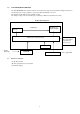
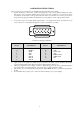
1-2 LCD MONITOR DESCRIPTION The LCD MONITOR will contain an main board, an Inverter module, keyboard, External Adapter which house the flat panel control logic, brightness control logic, DDC and DC-DC conversion The Inverter module will drive the backlight of panel . The Adapter will provides the 12V DC-power 4.16 Amp to Main-board,and Inverter module . Monitor Block Diagram Flat Panel and CCFL backlight CCFT Drive.
2. PRECAUTIONS AND NOTICES 2-1 ASSEMBLY PRECAUTION (1) Please do not press or scratch LCD panel surface with anything hard. And do not soil LCD panel surface by touching with bare hands ( Polarizer film, surface of LCD panel is easy to be flawed) In the LCD panel, the gap between two glass plates is kept perfectly even to maintain display characteristic and reliability.
3. OPERATING INSTRUCTIONS This procedure gives you instructions for installing and using the LCD monitor display. 1. Position the display on the desired operation and plug–in the power cord into External Adapter AC outlet. Three-wire power cord must be shielded and is provided as a safety precaution as it connects the chassis and cabinet to the electrical conduct ground.
4. ADJUSTMENT 4-1 ADJUSTMENT CONDITIONS AND PRECAUTIONS Adjustments should be undertaken only on following function : Contras , Brightness, Black level, Phase, Clock , H/V-position , Languages, Color-(7200,6500,User), Auto level, OSD-position, Languages, Reset 4-2 ADJUSTMENT METHOD Press MENU button to activate OSD Menu or make a confirmation on desired function, Press Left/Right button to select the function or done the adjustment. 1.
II. Gain adjustment : a. adjust 7200 color-temperature Set the Contrast of OSD function to 45 and Adjust Brightness to chroma 7120 Y=240 ±5 cd/m2 Switch the chroma-7120 to RGB-mode (with press “MODE” button ) Switch the MEM.channel to Channel 01 ( with up or down arrow on chroma 7120 ) The lcd-indicator on chroma 7120 will show x = 302 ±10, y = 319 ±10, Y = 200 ±5 cd/m2 Adjust the Color(user)Mode: RED on OSD window, until chroma 7120 indicator reached the value R=100 6.
2. Clock adjustment Set the Chroma at pattern 63 (cross-talk pattern) or WIN98/95 shut-down mode (dot-pattern). Adjust until the vertical-Stripe-shadow as wide as possible or no visible. This function is adjust the PLL divider of ADC to generate an accurate pixel clock Example : Hsyn = 31.5KHz Pixel freq. = 25.175MHz (from VESA spec) The Divider number is (N) = (Pixel freq.
5. 5-1 CIRCUIT-DESCRIPTION SPECIAL FUNCTION WITH PRESS-KEY A). press Menu button during 2 seconds along with plug-in the DC Power cord: That operation will set the monitor into “Factory- mode”, in Factory mode we can do the White balance adjustment with RS232 In Factory mode, OSD-screen will locate in left top of screen. Press POWER-button off to on once will quit from factory mode and back to user-mode. B).
MODULE-TPYE COMPONENT: 1. ADAPTER : CONVERSION-module to convert AC 110V-240V to 12VDC, with 4.16 AMP 2. INVERTER : CONVERSION-module to convert DC 12V to High-Voltage around 1650V, with frequency 30K-80Khz, 5.
5-3 SOFTWARE FLOW CHART I. Power-On Subroutine CHART POWER-ON START Initial MCU I/O, Interrupt vector & Ram Yes Initial 1.POC (backlight counter) 2. Clr all mode value Check Eeprom is empty ? No Check White-balance data(6500 & 7200) same with the backup OK data ? Check POC( backlight counter) data same with the backup data ? IF not same, overwrite the data with backup value.
II. MAIN SUBROTINE LOOP Main loop start Process Power-saving status ( according to below flow-chart result) ) Check GMZAN2 IFM status .is change or not.
6 A). INTERFACE-BOARD TROUBLE-SHOOTING CHART *Use the PC Win 98 white pattern, with some icon on it, and Change the Resolution to 640x480 60 Hz / 31 KHz **NOTICE : The free-running freq. of our system is 48 KHz / 60 Hz, so we recommend to use another resolution to do trouble shooting, this trouble shooting is proceed with 640x480 @60Hz 31Khz I. NO SCREEN APPEAR DC-Power Part Measured Input DC-voltage ( J1)= 12 V? Measured U305 AIC 1084 pin 2 = 3.3V? Measured U904 LT1117 pin 2= 3.
PANEL-POWER CIRCUIT Check the PPWR panel power relative circuit, R223,R224, Q200,U202(pin 5,6,7,8) In normal operation, when LED =green, R223 should =0 v, If PPWR no-response when the power switch Turn on and turn off, replace the U200-GMZAN2 NG check R225 should have response from 0V to 5V When we switch the power switch from on to off OK,R225 have response Yes NG, no Voltage Check U202 pin 1,3= 5V Measured the U202 pin 5,6,7,8= 5 V? Replace U202 ( Nmos, SI9953) OK NG OK Check U304 relative circ
II (a) THE SCREEN is Abnormal , stuck at white screen, OSD window can’t appear, but keyboard & LED was normal operation. At general, this symptom is cause by missing panel data or panel power, so we must check our wire-harness which connected to panel or the panel power controller (U202) NG Check if the Wire harness from CN603 loose? Check the wire on both Panel-side and Main board side. Tighten it.
II. (b)The screen had the Vertical Straight Line, might be stuck in Red, Green, Blue That symptom is cause by bad Panel issue ( might be the Source IC from Panel is cold solder or open loop ) so REPLACE THE PANEL TO NEW ONE.
POWER-BLOCK check **Note : the Waveform of U304 pin 2 can determined the power situation 1. 2. 3. stable rectangle waveform with equal duty, freq around 150K-158KHz that means all power of this interface board is in normal operation ,and all status of 5V & 3.3V is working well unstable or uneven rectangle waveform without same duty, that means ABNORMAL operation was happened, check 3.
III.ALL SCREEN HAS INTERFERENCES OR NOISE, CAN’T BE FIXED BY AUTO KEY ** NOTE: There is so many kind of interferences, 1). One is cause by some VGA-CARD that not meet VESA spec or power grounding too bad that influence our circuit 2).other is cause by external interferences, move the monitor far from electronic equipment.
There is interferences in DOS MODE NOTE :the criteria of doing AUTO-CONFIGURATION : must be a full-size screen, if the screen not full , the autoconfiguration will fail. So in dos mode ,just set your “CLOCK” in OSD-MENU to zero or use some EDITOR software which can full fill the whole screen (ex: PE2, HE) and then press “AUTO” Or you can use “DOS1.EXE” which attached in your Driver disk to optimize DOS mode performance V.
6 B). INVERTER –MODULE SPEC &TROUBLE SHOOTING CHART For LM720 model , use Hydis panel, and the INVERTER is made by SAMPO SAMPO Parts No: DIVTL0085-D42 AOC Parts No.: 79LL17-3-S I. CONNECTOR PIN ASSIGMENT: A) CON1: INPUT MODEL NO.: S5B-PH-SM3-TB PIN SYMBOL DESCRIPTION 1 Vin Input voltage: 12V 2 Vin Input voltage: 12V 3 ON/OFF ON: 3V OFF:0V 4 Dimming Dimming range (0V~+5.0V) 5 GND GND B) CON2,CON3,CON4,CON5: OUTPUT MODEL NO.
D) FUNCTION TEST CIRCUIT: 120KΩ 1 2 CON4 CON2 10Ω 1 VT-181 2 1 2 10Ω CON5 CON3 CON1 1 2 3 4 5 120KΩ 1 2 VT 120KΩ 120KΩ 10Ω 10Ω VT VT-181 22
II. TROUBLE SHOOTING BLOCK DIAGRAM A) NO POWER: CHECKED ON FUSE F1 Vin=12 PASS PASS TO CHANGED F1= 4.0A/63V FAIL TO CHECKED Q4 & Q6 VOUT = 9V FAIL TO CHANGED CH1: Q4/Q3/Q11 CH2: Q5/Q6/Q12 TO CHECKED L1/L2 INPUT 9V TO L1 OR L2 TO CHANGED CH1: Q7/Q8/D12/PT1 CH2: Q9/Q10/C13/PT2 FAIL FUNCTION TEST OK ! PASS B) HIGHT VOLTAGE PROTECTION: 1. SHORT R30 & OPEN LOAD FAIL 2. TEST PT1 OR PT2 OUTPUT PIN 7 H.
C) OUTPUT CURRENT ABNORMALITY: CHECK PWM FREQUNCY AT C6 CHIP THE OSCILLATOR FREQUNCY RANGE = 150 ~ 250 KHZ FAIL PASS D) TO CHANGE C6 CHIP OR IC CHIP FUNCTION TEST OK! ENBALE ABNORMALITY: IF ENABLE ABNORMALITY 1.
F) TRANSFORMER ABNORMALITY: IF TRANSFORMER ABNORMELITY TO CHECK C3 & C4 CHIP OUTLINE OR TRANSFORMER FAIL TO CHANGE C3 & C4 OR TRANSFORMER PASS FUNCTION TEST OK! G) INSTRUMENTS FOR TEST: 1. DC POWER SUPPLY GPS-3030D 2. AC VTVM VT:-181E 3. DIGITAL MULTIMERTER MODEL-34401 4. HIGHTVOLT PROB MODEL-1137A 5.
7.
BILL OF MATERIAL ========== ====================== ======================== 1 ADPC12416AF LCD ADAPTER ASS'Y 1 CBPC782KKZAE CONVERSION BOARD FOR T7 1 DCPC780A7 DC POWER BOARD FOR T780K 1 KEPC782KA6 KEY BOARD FOR T78* 1 7L 1 7 WOODEN PALLET 1 7L 1 60 WOODEN PALLET 1 15L5689 2 A GND CLAMP 1 15L5689 3 A GROUND CLAMP 1 15L5695 1 REAR BRACKET 1 15L5709 3 MAIN FRAME 1 15L5791 1 VESA BRACKET 1 33L4344 CA 1L HINGE COVER (L) 1 33L4344 CA 2L HINGE COVER(R) 1 33L4345 CA L CABLE COVER 1 33L4362 1 LENS 1 33L4447 CB L POW
1 45L 88607 PE BAG FOR MONITOR 1 50L 500 1 竕絬 1 50L 600 2 HANDLE1 1 50L 600 3 HANDLE2 1 52L 1186 SMALL TAPE 1 52L 1208 A TAPE 1 52L6019 1 独︹荡絫溅盿 1 52L6020 1 PROTECT FILM 」 1 79L L17 3 S INVERTER SAMPO 」 1 80L L17 2 CH ADAPTER VER:(01A﹁盡 1 85L 594 1 SHIELD MAIN 1 89L 174L1710E SIGNAL CABLE 」 1 89L402C18N GL POWER CORD 」 1 89L402C18N YH POWER CORD WALL OUT FOR 1 95L8014 5 14 HARNESS 1 95L8018 30 5 HARNESS 1 B1L1030 5128 SCREW 1 M1L 330 6128 SCREW 1 M1L1030 10128 SCREW 1 M1L1740 12128 SCREW 1 Q1L 340 12128 SCR
2 2 2 2 2 2 2 2 2 2 2 C916 C900 C900 C921 C922 C921 C922 C921 C922 C906 C904 65L305M3322F3 3300PF400VAC/250VAC 65L305M4722B2 4700 +-20% 400VAC ACFY 65L305M4722B3 4700PF +-20% 400VAC/25 67L 215102 3H 綯筿秆筿甧 1000UF 16V 67L 215102 3H 綯筿秆筿甧 1000UF 16V 67L 215102 3J 綯筿秆筿甧 1000UF/16V 67L 215102 3J 綯筿秆筿甧 1000UF/16V 67L 215102 3K 綯筿秆筿甧 1000UF/16V 67L 215102 3K 綯筿秆筿甧 1000UF/16V 67L305L101 4 100UF +-20% 25V 67L305S10114H HTR101M2GL33VR 2 71L 55 2 A FERRITE BEAD 6.5*5*1.7 2 71L 55 30 FERRITE BEAD 4.
3 IC902 3 IC905 3 IC902 3 IC905 3 C905 3 C920 3 C923 ---------## PAREN ---------- 56L 158 2 T 3PIN IC TL431C/T.I. 56L 158 2 T 3PIN IC TL431C/T.I. 56L 158 4 T A HTL431 56L 158 4 T A HTL431 65L 1K152 1T 1.
3 R906 3 R907 3 R908 3 R909 3 R910 3 R934 」 3 R901 」 3 R902 」 3 R903 」 3 R904 3 C913 3 C910 3 C914 3 C927 3 C908 3 C909 3 C911 3 C928 3 C929 3 C924 3 C912 3 C915 3 C926 3 ZD901 3 D904 3 D905 3 D904 3 D905 3 ZD901 ---------## PAREN ---------3 Q901 ---------## PAREN ---------3 R930 ---------## PAREN ---------- 61L1206304 CHIP 300K OHM 1/8W 61L1206304 CHIP 300K OHM 1/8W 61L1206304 CHIP 300K OHM 1/8W 61L1206304 CHIP 300K OHM 1/8W 61L1206304 CHIP 300K OHM 1/8W 61L1206471 CHIPR 470 OHM+-5% 1/8W 61L1206684 CHIPR
3 3 3 3 D911 D912 D911 D912 93L 60226 STPS 20H1.0 SGS-THOMSO 93L 60226 STPS 20H1.0 SGS-THOMSO 93L 60227 MBR20100CT 93L 60227 MBR20100CT 3 M1L1730 6128 SCREW M3x6 ---------- ---------------------- -----------------------## PAREN T NO : CBPC782KKZA E CONVERSION BOARD FO 2 AIC782KKZAE LCD MAIN BOARD FOR T78 2 CN303 33L3802 5H WAFER 5P RIGHT ANELE P 2 CN302 33L3802 9H WAFER 9P RIGHT ANELE P 2 R319 33L8009 2 2 PIN MIN.
3 3 3 3 3 3 3 3 3 3 3 3 3 3 3 3 3 3 3 3 3 3 3 3 3 3 3 3 3 3 3 3 3 3 3 3 3 3 3 3 3 3 3 3 U304 U305 U202 U904 U905 U401 U203 U300 Q200 Q304 RP300 RP301 JP301 L207 R203 R207 R208 R221 R229 R232 R233 R234 R310 R317 R340 R603 R200 R201 R202 R218 R219 R220 R227 R213 R214 R216 R217 R223 R224 R225 R300 R301 R311 R313 56L 563 1 56L 563 7 56L 566 6 56L 585 4 56L 585 5 56L 74F 14 56L1133 16 56L1133 33 57L 417 4 57L 417 4 61L 125103 61L 125472 61L0603000 61L0603000 61L0603000 61L0603000 61L0603000 61L0603000 61L06030
3 3 3 3 3 3 3 3 3 3 3 3 3 3 3 3 3 3 3 3 3 3 3 3 3 3 3 3 3 3 3 3 3 3 3 3 3 3 3 3 3 3 3 3 R315 R326 R327 R328 R329 R209 R210 R303 R204 R205 R206 JP202 JP302 L204 L205 C948 C949 C950 C951 C952 C953 C954 C955 C956 C957 C229 C230 C231 C232 C233 C234 C251 C606 C608 C614 C616 C201 C202 C204 C205 C207 C208 C209 C210 61L0603103 61L0603103 61L0603103 61L0603103 61L0603103 61L0603202 61L0603202 61L0603472 61L0603750 61L0603750 61L0603750 61L1206000 61L1206000 61L1206000 61L1206000 65L0603102 65L0603102 65L0603102 65
3 3 3 3 3 3 3 3 3 3 3 3 3 3 3 3 3 3 3 3 3 3 3 3 3 3 3 3 3 3 3 3 3 3 3 3 3 3 3 3 3 3 3 3 C211 C212 C213 C215 C217 C218 C219 C220 C221 C222 C223 C225 C226 C227 C228 C237 C244 C245 C246 C300 C304 C308 C311 C405 C601 C602 C604 C618 C619 C939 C940 C941 C942 C944 C946 C947 C250 C303 C306 CP301 CP302 C605 C607 C613 65L0603104 65L0603104 65L0603104 65L0603104 65L0603104 65L0603104 65L0603104 65L0603104 65L0603104 65L0603104 65L0603104 65L0603104 65L0603104 65L0603104 65L0603104 65L0603104 65L0603104 65L0603104 65
3 3 3 3 3 3 3 3 3 3 3 3 3 3 3 3 3 3 3 3 3 3 3 3 3 3 3 3 3 3 3 3 3 3 3 3 3 3 3 3 3 3 3 3 C615 C620 C200 C203 C206 C214 C216 C224 C305 C403 C603 C927 C928 C929 C930 C943 C313 C314 L200 L201 L202 L203 L300 L900 L601 L602 L603 L604 R215 R237 R238 L601 L602 L603 L604 R215 R237 R238 MTG U D200 D201 D208 D209 D210 67L 67L 67L 67L 67L 67L 67L 67L 67L 67L 67L 67L 67L 67L 67L 67L 67L 67L 71L 71L 71L 71L 71L 71L 71L 71L 71L 71L 71L 71L 71L 71L 71L 71L 71L 71L 71L 71L 30 93L 93L 93L 93L 93L 312100 312100 312101 3121
3 3 3 3 3 3 3 3 3 3 3 3 3 3 3 3 3 3 3 3 3 3 3 3 3 3 3 3 3 3 3 3 3 3 3 3 3 3 3 D200 D201 D208 D209 D210 D200 D201 D208 D209 D210 D300 D300 D303 D303 D303 D202 D203 D204 D205 D206 D207 D301 D302 D202 D203 D204 D205 D206 D207 D301 D302 D202 D203 D204 D205 D206 D207 D301 D302 93L 39147 TZMC5V6-GS08 93L 39147 TZMC5V6-GS08 93L 39147 TZMC5V6-GS08 93L 39147 TZMC5V6-GS08 93L 39147 TZMC5V6-GS08 93L 39149 MLL5232B BY FULL POWER 93L 39149 MLL5232B BY FULL POWER 93L 39149 MLL5232B BY FULL POWER 93L 39149 MLL5232B BY F
2 2 2 2 C71 JP2 JP2 F01 ---------## PAREN ---------- 2 SW101 2 SW102 2 SW103 2 SW104 2 SW105 2 LED1 2 JP801 ---------## PAREN ---------3 J101 3 J102 3 R109 3 R101 3 R102 3 R103 3 R104 3 R105 3 R106 3 R107 3 R108 ---------## PAREN ---------3 Q101 3 Q102 3 C101 ---------## PAREN ---------- 67L305L331 6 330UF +-20% 35V 88L 304 1S DC POWER JACK 88L 3041CE DC JACK 95L 90 23 TIN COATED 2 715L 919 2 15" 17" DC-IN BOARD ---------------------- -----------------------T NO : KEPC782KA6 KEY BOARD FOR T78* ---------
2 34L 918 CA B STAND BACK COVER 2 34L 919 CA B BASE 2 37L 448 1 LCD HINGE 2 Q1L 140 10128 SCREW 2 Q1L1030 10128 SCREW 2 Q1L1030 12128 SCREW ========== ====================== ======================== 9. 1 PCS 1 PCS 1 PCS 6 PCS 2 PCS 4 PCS ========= ===== POWER SYSTEM AND CONSUMPTION CURRENT ADAPTER MODULE Input AC 110V, 60Hz/240V, 50Hz Output DC 12V 5A INVERTER MODULE Input DC 12V Output AC 1500V/30K-80KHz Current 14mA Main board power system LM2596S-5, 12V to 5V (5A SPEC) 5V AIC1084 5V to 3.
10. PCB LAYOUT MAIN PCB LAYOUT DDC chip RT9164 5V to 2.5v LVDS power ( LT1117) 5V to 3.3v Input Connector LVDS Gmzan2 AIC1084 5V to 3.
11. SCHEMATIC DIAGRAM TOP-LEVEL FLOW Power block POWER +3.3V +3.3V +12V 12V +2.5V +2.5V +5.0V +3.3V +2.5V +5V AIC1084-3.3V RT9164-2.5V LM2596-5.0V .Gmzan2 block LVDS block +3.3V R ERED ERED[0-7] EGRN EGRN[0-7] TX0-/+E EBLU[0-7] TX1-/+E DENABLE TX2-/+E RED EBLU G GREEN B BLUE PDISPE H-SYNC HSYNC/CS V-SYNC VSYNC +5V LVDS1 PVS PVS TX3-/+E PHS PHS TX0-/+E TX1-/+E TX2-/+E TX3-/+E TXC-/+E TXCLKIN /PWRDWN PCLK LVDSEN NT7181 PANEL(HYUNDAI-300) VCC VCC +3.3V INPUT ZAN2 +2.
+D5V +3.3V GMZAN2 Block +3.3V L200 C956 2 +B2.
AVDD_3.3 LVDS Block C601 EVEN PD36 PD37 PD[0..5] PD38 PD39 PD[6..11] PD40 PD41 PD[12..17] PD36 PD37 PD0 PD1 PD2 PD3 PD4 PD5 51 52 54 55 56 3 50 2 PD38 PD39 PD6 PD7 PD8 PD9 PD10 PD11 4 6 7 11 12 14 8 10 PD40 PD41 PD12 PD13 PD14 PD15 PD16 PD17 15 19 20 22 23 24 16 18 25 27 28 30 31 PCLKA C602 C603 TXIN0 TXIN1 TXIN2 TXIN3 TXIN4 TXIN6 TXIN27 TXIN5 GND EDGE PWRDWN TXOUT0TXOUT0+ TXOUT1TXOUT1+ TXOUT2TXOUT2+ TXOUT3TXOUT3+ TXIN7 TXIN8 TXIN9 TXIN12 TXIN13 TXIN14 TXIN10 TXIN11 + 0.
+5V MCU Block +5V +5V R431 R239 10 K(OP) R235 4.7K(OP) 4.7K(OP) R238 0 MUTE 20MHz 22 33 pF 10 K 2 10 K CN302 KEY1(ORANGE?) KEY2(GREEN?) RP301 8 1 7 2 6 3 5 4 4.7K Ohm C305 C304 100uF 0.1 uF 4 R303 4.
+5V +12V U304 LM2596S-5.0 / Si8050 FB301 TO263 2 1 4 3 C307 C308 330 uF/35V 0.1 uF VIN FBK Vout 4 2 T300 5 5 3 6 1 /ON GND J1 +12V POWER C309 D300 33 uH(OP) INDUCTOR-P C941 0.1 uF 330 uF/35V B320 L906 GND F 1 2 CHOKE GND POWER Block GND +5V JP301(OP) +A5V 3 2 1 L905 1 2 CHOKE +A5V +3.3V C945 GND 470uF/16V +12V C952 GND +5V +5V +D5V PW5V-ON Q202 MMBT3904 D1 D1 D2 D2 8 7 6 5 U305 0 AIC 1084 L300 3 4431 C310 330 uF/35V C311 0.