s
Safety........................................................................................................................................................................ 3 National Conventions......................................................................................................................................... 3 Power ................................................................................................................................................................
Safety National Conventions The following subsections describe notational conventions used in this document. Notes, Cautions, and Warnings Throughout this guide, blocks of text may be accompanied by an icon and printed in bold type or in italic type. These blocks are notes, cautions, and warnings, and they are used as follows: NOTE: A NOTE indicates important information that helps you make better use of your computer system.
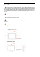
Power The monitor should be operated only from the type of power source indicated on the label. If you are not sure of the type of power supplied to your home, consult your dealer or local power company. The monitor is equipped with a three-pronged grounded plug, a plug with a third (grounding) pin. This plug will fit only into a grounded power outlet as a safety feature.
Installation Do not place the monitor on an unstable cart, stand, tripod, bracket, or table. If the monitor falls, it can injure a person and cause serious damage to this product. Use only a cart, stand, tripod, bracket, or table recommended by the manufacturer or sold with this product. Follow the manufacturer’s instructions when installing the product and use mounting accessories recommended by the manufacturer. A product and cart combination should be moved with care.
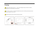
Cleaning Clean the cabinet regularly with cloth. You can use soft-detergent to wipe out the stain, instead of strong-detergent which will cauterize the product cabinet. When cleaning, make sure no detergent is leaked into the product. The cleaning cloth should not be too rough as it will scratch the screen surface. Please disconnect the power cord before cleaning the product.
Other If the product is emitting a strange smell, sound or smoke, disconnect the power plug IMMEDIATELY and contact a Service Center. Make sure that the ventilating openings are not blocked by a table or curtain. Do not engage the LCD monitor in severe vibration or high impact conditions during operation. Do not knock or drop the monitor during operation or transportation.
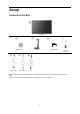
Setup Contents of the Box Monitor CD Manual Power Cable USB Cable Stand Wire holder DP Not all signal cables (Audio,Analog, DVI, DP, USB and HDMI cables) will be provided for all countries and regions. Please check with the local dealer or AOC branch office for confirmation.
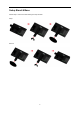
Setup Stand & Base Please setup or remove the base following the steps as below.
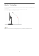
Adjusting Viewing Angle For optimal viewing it is recommended to look at the full face of the monitor, then adjust the monitor's angle to your own preference. Hold the stand so you will not topple the monitor when you change the monitor's angle. You are able to adjust the monitor's angle from -5° to 20 °. NOTE: Do not touch the LCD screen when you change the angle. It may cause damage or break the LCD screen.
Connecting the Monitor Cable Connections In Back of Monitor and Computer: 1 USB2.0 + fast charging 2 USB2.0 3 USB3.0 4 USB input 5 Display port 6 DC Power To protect equipment, always turn off the PC and LCD monitor before connecting. 1 Connect the power cable to the AC port on the back of the monitor. 2 Connect one end of the DP cable to the back of the monitor and connect the other end to the computer’s DP port. 3 Turn on your monitor and computer.
System requirement 1. G-system function: Compatible Graphics Card: GeForce GTX 650 Ti Boost or higher (for a list of compatible graphics cards, please visit www.nvidia.com/G-sync) Driver: GeForce 331.58 or higer OS: Windows 7/8/8.1 2. 3D function: The G-Sync monitor is NVIDIA 3D Vision Ready monitor. To enable 3D function, NVIDIA 3D version kit is required. NVIDIA 3D version kit requirement for stereoscopic 3D experience for a list of compatible graphics cards, please visit www.nvidia.
Wall Mounting Preparing to Install An Optional Wall Mounting Arm. This monitor can be attached to a wall mounting arm you purchase separately. Disconnect power before this procedure. Follow these steps: 1 Remove the base. 2 Follow the manufacturer's instructions to assemble the wall mounting arm. 3 Place the wall mounting arm onto the back of the monitor. Line up the holes of the arm with the holes in the back of the monitor. 4 Insert the 4 screws into the holes and tighten.
Adjusting Setting Optimal Resolution Windows Vista For Windows Vista: 1 Click START. 2 Click CONTROL PANEL. 3 Click Appearance and Personalization.
5 Click Display Settings. 6 Set the resolution SLIDE-BAR to Optimal preset resolution.
Windows XP For Windows XP: 1 Click START. 2 Click SETTINGS. 3 Click CONTROL PANEL. 4 Click Appearance and Themes. 5 Double click DISPLAY.
6 Click SETTINGS. 7 Set the resolution SLIDE-BAR to Optimal preset resolution. Windows ME/2000 For Windows ME/2000: 1 Click START. 2 Click SETTINGS. 3 Click CONTROL PANEL. 4 Double click DISPLAY. 5 Click SETTINGS. 6 Set the resolution SLIDE-BAR to Optimal preset resolution.
Windows 8 For Windows 8: 1. Right click and click All apps at the bottom-right of the screen. 2. Set the “View by” to “Category”. 3. Click Appearance and Personalization.
4. Click DISPLAY. 5. Set the resolution SLIDE-BAR to 1920x1080.
Hotkeys 1 (Dialpoint OFF\ON) / Exit 2 Dialpoint selection menu / < 3 ULMB / > 4 Menu / Enter 5 Power (Dialpoint Off\On) / Exit When the OSD is closed, press (Dialpoint OFF\ON) button will be on or off Dialpoint type. When the OSD is not closed,press Exit button to save user data. < Dialpoint Selection Menu Press the Dialpoint selection menu key to active the Dialpoint menu . Press < or > button to choose a different Frosshair type.
OSD Setting Basic and simple instruction on the control keys. MENU-button to activate the OSD window. 1) Press the 2) Press < or > to navigate through the functions. Once the desired function is highlighted, press the MENU-button to activate it . press < or > to navigate through the sub-menu functions. Once the desired function is highlighted, press 3) MENU-button to activate it. Press < or > to change the settings of the selected function. Press any other function, repeat steps 2-3.
Luminance (3D function disable) Luminance (3D function enable) Contrast @ NVIDIA LightBoost Gamma Luminance 50 Color Setup tm Gamma 1 OSD Setup Off Extra Overdrive 1. Press (Menu) to display menu. 2. Press < or > to select 3. 4. Press < or > to select submenu, and press Press < or > to adjust. 5. Press (Luminance), and press to enter. to exit. 22 to enter.
Backlight Adjustment Brightness Each step will increase / Recall 0-100 Brightness Value 90 decrease value by 1 Contrast from Recall Digital-register. Luminance Each step will Contrast increase / 0-100 decrease value Contrast by 1 Value 50 Gamma Overdrive Gamma Gamma1 (2.2) Adjustment Gamma2 (2.0) Recall Gamma3 (2.4) Gamma1 Value adjust the response time Strong/Medium/Light/Weak/Off Note: When the 3D function starts brightness options are replaced by NVIDIA Light Boost options.
Color Setup 1. Press (Menu) to display menu. 2. Press < or > to select 3. Press < or > to select submenu, and press 4. Press < or > to adjust. 5. Press to enter. to exit. Recall Warm Color Warm Temperature from (6500K) Recall Normal Color Temperature from (7300K) Setup N/A EEPROM. Recall Cool Color Cool Color Temp N/A EEPROM. Normal Color to enter. (Color Setup), and press Temperature from (9300K) N/A EEPROM. Recall sRGB Color with Temperature from sRGB EEPROM. Warm.
Red gain from Red Digital-register. N/A Each step will increase 0-100 R/G/B / decrease value by 1 Green N/A Green gain from 0-100 Digital-register. reset Blue gain from N/A Each step will increase / decrease value by 1 Note: (1) In the sRGB color temperature, brightness, contrast is not adjustable (2) OSD menu color will change with the picture color change 25 is 50) will modified by / decrease value by 1 Blue value(default not be Each step will increase Digital-register.
OSD Setup 1. Press (Menu) to display menu. 2. Press < or > to select 3. 4. Press < or > to select submenu, and press Press < or > to adjust. 5. Press (OSD Setup), and press to enter. to enter. to exit. English Français Español Português Deutsch Italiano OSD Setup Language No need to recall language while press “RESET”. Set OSD display Nederlands language to English.
Adjust the OSD timeout. Timeout Each step will increase / 5-120 Recall 10 Value decrease value by 5 Adjust the horizontal H. Position position of the OSD. Each step will increase / 0-100 Recall 100 Value decrease value by 25 Adjust the vertical V. Position position of the OSD.
Extra 1. Press (Menu) to display menu. 2. Press < or > to select 3. Press < or > to select submenu, and press 4. Press < or > to adjust. 5. Press (Extra), and press to enter. to enter. to exit.
Clear each old status of Auto-configuration and set the color temperature YES to Warm N/A Reset Do not execute reset, return to main menu. Extra G_sync NO function disable and timing V freq >=85hz On Off ULMB G_sync function enable or display card do not support G_sync Off function Note : 1) 2) The OSD language is not be reseted. ULMB mode cannot be adjusted when G_sync function enable or display card do not support G_sync function.
LED Indicator Status LED Color Full Power Mode Green or Blue Active-off Mode Orange or red 30
Driver Monitor Driver Windows 8 1. Start Windows® 8 2. Right click and click All apps at the bottom-right of the screen. 3. Click on the “Control panel” icon 4. Set the “View by” to “Large icons” or “Small icons”.
5. Click on the “Display” icon. 6. Click on the “Change display settings” button. 7. Click the “Advanced Settings” button.
8. Click the “Monitor” tab and then click the “Properties” button. 9. Click the “Driver” tab. 10. Open the “Update Driver Software-Generic PnP Monitor” window by clicking on “Update Driver... “ and then click the "Browse my computer for driver software" button.
11. Select "Let me pick from a list of device drivers on my computer". 12. Click the “Have Disk” button. Click on the “Browse” button and navigate to the following directory: X:\Driver\module name (where X is the drive letter designator for the CD-ROM drive). 13. Select the "xxx.inf" file and click the “Open” button. Click the “OK” button. 14. Select your monitor model and click the “Next” button. The files will be copied from the CD to your hard disk drive. 15. Close all open windows and remove the CD.
Windows 7 1.Start Windows® 7 2.Click on the 'Start' button and then click on 'Control Panel'. 3. Click on the 'Display' icon. 4.Ckick on the “Change display settings” button.
5.Click the “Advanced Settings” button. 6.Click the “Monitor” tab and then click the “Properties” button. 7.Click the “Driver” tab.
8. Open the "Update Driver Software-Generic PnP Monitor" window by clicking on “Update Driver... “and then click the "Browse my computer for driver software" button. 9. Select "Let me pick from a list of device drivers on my computer". 10. Click the “Have Disk” button. Click on the “Browse” button and navigate to the following directory: X:\Driver\module name (where X is the drive letter designator for the CD-ROM drive).
11. Select the "xxx.inf" file and click the “Open” button. Click the “OK” button. 12. Select your monitor model and click the “Next” button. The files will be copied from the CD to your hard disk drive. 13. Close all open windows and remove the CD. 14. Restart the system. The system will automatically select the maximum refresh rate and corresponding Color Matching Profiles.
Windows Vista 1. Click "Start " and "Control Panel". Then, double-click on "Appearance and Personalization". 2. Click "Personalization" and then "Display Settings". 3. Click "Advanced Settings...".
4. Click "Properties" in the "Monitor" tab. If the "Properties" button is deactivated, it means the configuration for your monitor is completed. The monitor can be used as is. If the message "Windows needs..." is displayed, as shown in the figure below, click "Continue". 5. Click "Update Driver..." in the "Driver" tab. 6. Check the "Browse my computer for driver software" checkbox and click "Let me pick from a list of device drivers on my computer". 7. Click on the 'Have disk...
Windows XP 1. Start Windows® XP 2. Click on the 'Start' button and then click on 'Control Panel'. 3. Select and click on the category ‘Appearance and Themes’ 4. Click on the 'Display' Item.
5. Select the 'Settings' tab then click on the 'Advanced' button. 6. Select 'Monitor' tab - If the 'Properties' button is inactive, it means your monitor is properly configured. Please stop installation. - If the 'Properties' button is active, click on 'Properties' button. Please follow the steps below. 7. Click on the 'Driver' tab and then click on 'Update Driver...' button.
8. Select the 'Install from a list or specific location [advanced]' radio button and then click on the 'Next' button. 9. Select the 'Don't Search. I will choose the driver to install' radio button. Then click on the 'Next' button. 10. Click on the 'Have disk...' button, then click on the 'Browse...' button and then select the appropriate drive F: (CD-ROM Drive). 11. Click on the 'Open' button, then click the 'OK' button. 12. Select your monitor model and click on the 'Next' button.
Windows 2000 1. Start Windows® 2000 2. Click on the 'Start' button, point to 'Settings', and then click on 'Control Panel'. 3. Double click on the 'Display' Icon. 4. Select the 'Settings' tab then click on 'Advanced...'. 5. Select 'Monitor' - If the 'Properties' button is inactive, it means your monitor is properly configured. Please stop installation. - If the 'Properties' button is active. Click on 'Properties' button. Please follow the steps given below. 6.
Troubleshoot Problem & Question Possible Solutions Power LED Is Not ON Make sure the power button is ON and the Power Cord is properly connected to a grounded power outlet and to the monitor. Is the power cord connected properly? Check the power cord connection and power supply. Is the cable connected correctly? (Connected using the DP cable) No images on the screen If the power is on, reboot the computer to see the initial screen (the login screen), which can be seen.
Specification General Specification Panel Model name G2460PG Driving system TFT Color LCD Viewable Image Size 61.0 cm diagonal Pixel pitch 0. 27675 mm(H) x 0. 27675 mm(V) Video DP Interface Separate Sync. H/V TTL Display Color 16.7M Colors Dot Clock 325.08MHz Horizontal scan range 30kHz~160kHz Horizontal scan Size(Maximum) 531.36 mm Resolution Vertical scan range 30Hz~150Hz Vertical scan Size(Maximum) 298.
Preset Display Modes STANDARD HD HORIZONTAL VERTICAL FREQUENCY(kHZ) FREQUENCY(Hz) 1920×1080@60Hz 67.500 60.000 1920×1080@100Hz 113.300 100 1920×1080@85Hz 96.513 84.884 1920×1080@120Hz 137.260 119.982 1920×1080@144Hz 158.
20-Pin Color Display Signal Cable Pin No. Signal Name Pin No.
Plug and Play Plug & Play DDC2B Feature This monitor is equipped with VESA DDC2B capabilities according to the VESA DDC STANDARD. It allows the monitor to inform the host system of its identity and, depending on the level of DDC used, communicate additional information about its display capabilities.
Regulation FCC Notice FCC Class B Radio Frequency Interference Statement WARNING: (FOR FCC CERTIFIED MODELS) NOTE: This equipment has been tested and found to comply with the limits for a Class B digital device, pursuant to Part 15 of the FCC Rules. These limits are designed to provide reasonable protection against harmful interference in a residential installation.
WEEE Declaration Disposal of Waste Equipment by Users in Private Household in the European Union. This symbol on the product or on its packaging indicates that this product must not be disposed of with your other household waste.Instead, it is your responsibility to dispose of your waste equipment by handing it over to a designated collection point for the recycling of waste electrical and electronic equipment.
Service EU WARRANTY FOR AOC MONITORS LIMITED THREE-YEAR WARRANTY* For AOC LCD Monitors sold within Europe, AOC International (Europe) B.V. warrants this product to be free from defects in material and workmanship for a period of Three (3) years after the original date of consumer purchase. During this period, AOC International (Europe) B.V. will, at its option, either repair the defective product with new or rebuilt parts, or replace it with a new or rebuilt product at no charge except as *stated below.
All AOC LCD Monitors are produced according to the ISO 9241-307 Class 1 pixel policy standards. ALL EXPRESS AND IMPLIED WARRANTIES FOR THIS PRODUCT (INCLUDING THE WARRANTIES OF MERCHANTABILITY AND FITNESS FOR A PARTICULAR PURPOSE) ARE LIMITED IN DURATION TO A PERIOD OF THREE (3) YEARS FOR PARTS AND LABOR FROM THE ORIGINAL DATE OF CONSUMER PURCHASE. NO WARRANTIES (EITHER EXPRESSED OR IMPLIED) APPLY AFTER THIS PERIOD. AOC INTERNATIONAL (EUROPE) B.V.
Warranty Statement for North & South America (excluding Brazil) WARRANTY STATEMENT for AOC Color Monitors Including those Sold within North America as Specified Envision Peripherals, Inc. warrants this product to be free from defects in material and workmanship for a period of three (3) years for parts & labor and one (1) year for CRT Tube or LCD Panel after the original date of consumer purchase. During this period, EPI ( EPI is the abbreviation of Envision Peripherals, Inc.
ALL EXPRESS AND IMPLIED WARRANTIES FOR THIS PRODUCT (INCLUDING THE WARRANTIES OF MERCHANTABILITY AND FITNESS FOR A PARTICULAR PURPOSE) ARE LIMITED IN DURATION TO A PERIOD OF THREE (3) YEARS FOR PARTS AND LABOR AND ONE (1) YEAR FOR CRT TUBE OR LCD PANEL FROM THE ORIGINAL DATE OF CONSUMER PURCHASE. NO WARRANTIES (EITHER EXPRESSED OR IMPLIED) APPLY AFTER THIS PERIOD.