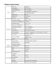
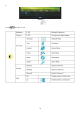
21.5" LCD Monitor AOC E2250SWDN Service Service Service Horizontal Frequency 30 - 83kHz Table of Contents Description Page Description Page Table of Contents…………………..…………………..…...1 6.Schematic…………..….........................................30 Revision List.…...................................................……......2 6.1.Main Board..…….…...........................................30 Important Safety Notice.….….............................……......3 1.Monitor Specification..........................
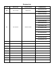
Revision List Version Release Date Revision History A00 Feb.-21-2012 Initial release TPV Model Name TIBKN22QAGE6HNE TIBKN22KAGE6HNE TIAKN22LAGACHNE TIB2N22BAGA1HNE TIB2N22BDFA1HNE TIB2N22KAGE6HNE TIB2N22QAGE6HNE TIBKN22BDFA1HNE A01 Feb.
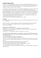
Important Safety Notice Proper service and repair is important to the safe, reliable operation of all AOC Company Equipment. The service procedures recommended by AOC and described in this service manual are effective methods of performing service operations. Some of these service operations require the use of tools specially designed for the purpose. The special tools should be used when and as recommended.
1.
2.LCD Monitor Description The LCD MONITOR will contain a main board, a power board, and a key board which house the flat panel control logic, brightness control logic and DDC. The power board will provide AC to DC Inverter voltage to drive the backlight of panel and the main board chips each voltage.
3. Operating Instructions 3.1 General Instructions Press the power button to turn the monitor on or off. The other control knobs are located at front panel of the monitor (See Figure ). By changing these settings, the picture can be adjusted to your personal preferences. * The power cord should be connected. * Press the power button to turn on the monitor. The power indicator will light up. 3.2 Control Buttons and Connections Power Press the Power button to turn on/off the monitor.
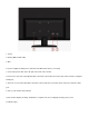
1. Power 2. Analog (DB-15 VGA cable) 3. DVI To protect equipment, always turn off the PC and LCD monitor before connecting. 1 Connect the power cable to the AC port on the back of the monitor. 2 Connect one end of the 15-pin D-Sub cable to the back of the monitor and connect the other end to the computer's D-Sub port. 3. Connect one end of the DVI cable to the back of the monitor and connect the other end to the computer‟s DVI port. 4 Turn on your monitor and computer.
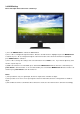
3.3 OSD Setting Basic and simple instruction on the control keys. 1) Press the MENU-button to activate the OSD window. 2) Press - or + to navigate through the functions. Once the desired function is highlighted, press the MENU-button to activate it. press - or + to navigate through the sub-menu functions. Once the desired function is highlighted, press MENU-button to activate it. 3) Press - or + to change the settings of the selected function. Press AUTO to exit.
Luminance 1 Press (Menu) to display menu. 2 Press or to select (Luminance), and press to enter. 3 Press or to select submenu, and press or to adjust. to enter.
5 Press two times to exit.
Image Setup 1 Press (Menu) to display menu. 2 Press or to select (Image Setup), and press to enter. 3 Press or to select submenu, and press or to adjust. to enter.
5 Press two times to exit.
Color Setup 1 Press (Menu) to display menu. 2 Press or to select (Color Setup), and press to enter. 3 Press or to select submenu, and press or to adjust. to enter.
5 Press two times to exit.
Picture Boost 1 Press (Menu) to display menu. 2 Press or to select (Picture Boost), and press or to select submenu, and press or to adjust. 3 Press to enter. 4 Press 15 to enter.
5 Press two times to exit.
OSD Setup 1 Press (Menu) to display menu. 2 Press or to select (OSD Setup), and press or to select submenu, and press or to adjust. 3 Press to enter. 4 Press 17 to enter.
5 Press two times to exit.
Extra 1 Press (Menu) to display menu. 2 Press or to select (Extra), and press to enter. 3 Press or to select submenu, and press to enter. 4 Press or to adjust.
5 Press two times to exit.
Exit 1 Press (Menu) to display menu. 2 Press or to select (Exit), and press to enter.
LED Indicators Status LED Color Full Power Mode Green or Blue Active-off Mode Orange or red e-Saver Welcome to use AOC e-Saver monitor power management software! The AOC e-Saver features Smart Shutdown functions for your monitors, allows your monitor to timely shutdown when PC unit is at any status (On, Off, Sleep or Screen Saver); the actual shutdown time depends on your preferences (see example below). Please click on "driver/e-Saver/setup.
Screen+ Welcome to "Screen+" software by AOC, Screen+ software is a desktop screen splitting tool, it splits the desktop into different panes, each pane displays a different window. You only need to drag the window to a corresponding pane, when you want to access it. It supports multiple monitor display to make your task easier. Please follow the installation software to install it.
4. Input/Output Specification 4.
4.
4.3 Panel Specification 4.3.1 General Features HM215WU1-500 is a color active matrix TFT LCD module using amorphous silicon TFT's (Thin Film Transistors) as an active switching devices. This module has a 21.5 inch diagonally measured active area with FHD resolutions (1920 horizontal by 1080 vertical pixel array). Each pixel is divided into RED, GREEN, BLUE dots which are arranged in vertical stripe and this module can display 16.7M colors.
The current draw and power consumption specified is for VDD=5.0V, Frame rate=75Hz. Test Pattern of power supply current a) Typ : Color Bar pattern b) Max : Skip Sub Pixel Pattern 2. Duration of rush current is about 2 ms and rising time of VDD is 520 μs ± 20 % 4.3.4 Optical Characteristics [VDD = 5.
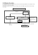
5. Block Diagram 5.1 Main Board 04.SCALER 02.INPUT +5V EDID_WP +5V EDID_WP R0+ R0SOG_DET G0+ G0B0+ B0AHS0 AVS0 DDCSDA1 DDCSCL1 VGA_CABLE_DET R0+ R0SOG_DET G0+ G0B0+ B0AHS0 AVS0 DDCSDA1 DDCSCL1 VGA_CABLE_DET R0+ R0SOG_DET G0+ G0B0+ B0AHS0 AVS0 VCC3.3 DDCSDA1 DDCSCL1 PA[0..9] VCC1.8 +5V VCC1.8 +5V 05.PANEL INTERFACE PA[0..9] PA[0..9] VGA_CABLE_DET 02.D-SUB INPUT PB[0..9] EDID_WP VCC3.3 PB[0..9] PB[0..9] EDID_WP P_SCL P_SCL P_SDA P_SDA VLCD VLCD 05.PANEL INTERFACE 03.
5.2 Power Board EMI filter Bridge Rectifier and Filter Transformer (T901) Rectifier diodes 14.5V 5V Start Resistor (R908,R911) Feedback PWM Control LD7576AGR (U901) Circuit Power Switch (Q901) Photo coupler Regulator (U902) 14.
6. Schematic 6.1 Main Board DDCSCL1 R101 DDCSCL_A 100R 1/16W 5% VSIN0 5 DDCSCL1 14 13 DDCSDA1 R106 DDCSDA_A 100R 1/16W 5% 5 DDCSDA1 DET_VGA D-SUB 15P 10 5 9 4 8 3 7 2 6 1 15 HSIN0 CN101 12 11 R102 100R 1/16W 5% VGA_CABLE_DET VGA_CABLE_DET 5 VGA_5V VGA_5V BIN0BIN0 GIN0GIN0 RIN0RIN0 R103 0R05 1/16W BIN0 ZD101 RLZ5.
26 25 GND GND U104 1 2 3 DAT0+ DAT0DAT1+ DAT1DAT2+ DAT2- 1K 1/16W 5% NC Q101 CH1 CH4 VN VP CH2 CH3 6 5 4 ESD_DVI ESD_DVI 2 1 D102 BAV70 R134 R135 R136 R137 R138 R139 ESD_DVI 10R 10R 10R 10R 10R 10R 1/16W 1/16W 1/16W 1/16W 1/16W 1/16W 5% 5% 5% 5% 5% 5% RX0+ RX0RX1+ RX1RX2+ RX2- 5 5 5 5 5 5 8 7 6 5 DDCSCL2 5 DDCSDA2 5 EDID_WP DCLK+ DCLK- ESD_DVI C116 U105 C115 RLZ5.
PB0 PB1 PB2 PB3 PB4 PB5 PB6 PB7 PB8 PB9 C403 100N 16V R402 R403 LVB3P LVB3M LVBCKP LVBCKM LVB2P LVB2M LVB1P LVB1M LVB0P LVB0M 1 3 5 7 NC/2K2 1/16W 5% NC/2K2 1/16W 5% 2 4 6 8 VCC3.3 CN401 NC/8PIN VCC3.3 C421 4.7UF 10V C0805 C418 100N 16V C419 100N 16V RX2+ RX2RX1+ RX1RX0+ RX0RXC+ RXC- RX2+ RX2RX1+ RX1RX0+ RX0RXC+ RXC- 3 AHS0 3 AVS0 C422 100N 16V 3 SOG_DET 3 G0+ 3 G0- C423 4.
PA[0..9] PB[0..9] 5 PB[0..
+5V +5V VCC3.3 C701 R702 4K7 1/16W 5% +5V 4 INPUT OUTPUT 4 FB701 0 OHM +-5% 1/8W 2 1 ADJ/GND + VCC3.3 5 100N 16V C704 3,4,5 +5V DIM ON/OFF AZ1117H-3.3TRG1 100uF16V C702 NC/CONN VCC3.3 U701 3 C703 100N 16V 6 5 4 3 2 1 100N 16V +5V 3,4,5 CN701 R703 9 8 7 6 5 4 3 2 1 100R 1/16W 5% Adj_BACKLIGHT 5 + C706 U702 VCC3.
6.2 Power Board 715G4744P01000001C ! 1 R929 100 OHM 1/4W C916 R930 100 OHM 1/4W 2N2 500V C928 2N2 500V F801 0R05 1/4W +14.
FB802 D801 L801 1 2 1 2 CN803 +14.5V 10 OHM 1/8W 47UH BEAD 8 7 6 5 Q801 C814 100N 50V APM8005KCTRG 1 2 C810 0.47UF 50V S1 G1 S2 G2 R801 10K 1/8W SK310B 1 2 3 4 R805 C802 10N 50V 1 R806 C803 1N 50V C806 220N 50V R803 300K 1/8W C815 CN801 1 OHM +-5% 1/8W 9 10 11 12 13 14 15 16 R822 NC NC/CONN R808 1 OHM +-5% 1/8W C808 100PF 500V VIN VREF STATUS LDR SSTCMP ISW PWM ENA ISEN1 RT ISEN2 OVP GND ISET ISEN3 ISEN4 8 7 6 5 4 3 2 1 6 5 4 3 2 1 R817 100 OHM 1/4W R812 0.
7. PCB Layout 7.
7.
7.
8. Maintainability 8.1 Equipments and Tools Requirement 1. Voltmeter. 2. Oscilloscope. 3. Pattern Generator. 4. DDC Tool with an IBM Compatible Computer. 5. Alignment Tool. 6. LCD Color Analyzer. 7. Service Manual. 8. User Manual.
8.
2.
3.
4.
9.White- Balance, Luminance Adjustment Approximately 30 minutes should be allowed for warm up before proceeding white balance adjustment. How to setting MEM channel you can reference to chroma 7120 user guide or simple use “SC” key and “NEXT” Key to modify xyY value and use “ID” key to modify the TEXT description Following is the procedure to do white-balance adjust . 1. Setting the color temp. A. 6500K: x=313±20 ,y=329±20 Warm color temp. parameter is B. 7300K Normal color temp.
B. Adjust Normal (7300K) color-temperature 1. Switch the chroma-7120 to RGB-Mode (with press “MODE” button) 2. Switch the MEM.channel to Channel 4(with up or down arrow on chroma 7120) 3. The LCD-indicator on chroma 7120 will show x=301±20 ,y=317±20 4. Adjust the RED on factory window until chroma 7120 indicator reached the value R=100 5. Adjust the GREEN on factory window until chroma 7120 indicator reachedthe value G=100 6.
10.
11. BOM List Note: The parts information listed below are for reference only, and are subject to change without notice. Please go to http://cs.tpvaoc.cn/hello1.asp for the latest information. TIBKN22QAGE6HNE Location Part No.
H45G 77 6 PE PACKING H45G 87 1 25 EPE COVER H52G1801 16006 insulating sheet H70G21C161507A CD MANUAL e2250SWDN KEPCAHB5 KEY BOARD PLPCBB581AHD1 POWER BOARD Q40G 58162435A LABEL Q45G 76 28 H A P.E. BAGx320x210x0.04 Q50G 4 10 TIE (Y1900221) Q52G 1185 99 BIG CARTON TAPE FOR AOC M05201 Q52G100202500A00JY AL FOIL M05203 Q52G100204500A00JY AL FOIL M05202 Q52G100204500A00JY AL FOIL Q52G6019 14 TAPE S95G179T30NE34 FFC CABLE 30P 190mm P1.
L906 073G 253191 L801 073G 253214 DN CHOKE COIL 47UH 10% LZ.CC013.G01 2.5A T901 080GL22T X'FMR 490UH 7% 4UH YUVA-1656 CN901 H 3 N3 087G 501 48 S IND CHOKE 1.1uH DADON AC SOCKET 3PIN + 3 Hole D902 093G 60335 DIODE SR515 5A/150V DO-201AD D901 093G 60335 DIODE SR515 5A/150V DO-201AD CN902 095G 825 9T518 HARNESS 9P-9P 120MM CN902 095G 825 9W518 HARNESS 9P-9P 120MM 0Q1G 340 SCREW Q1-SELF TAPING SCREW :Q CN804 BD901 8140 311GW200A06ABX WAFER 2.
R117 061G0402000 JT RST CHIPR MAX0R05 1/16W TZAI YUAN R110 061G0402000 JT RST CHIPR MAX0R05 1/16W TZAI YUAN R109 061G0402000 JT RST CHIPR MAX0R05 1/16W TZAI YUAN R104 061G0402000 JT RST CHIPR MAX0R05 1/16W TZAI YUAN R103 061G0402000 JT RST CHIPR MAX0R05 1/16W TZAI YUAN R141 061G0402100 JT RST CHIP 10R 1/16W 5% TZAI YUAN R140 061G0402100 JT RST CHIP 10R 1/16W 5% TZAI YUAN R139 061G0402100 JT RST CHIP 10R 1/16W 5% TZAI YUAN R138 061G0402100 JT RST CHIP 10R 1/16W 5% TZAI YUAN R137 0
R432 061G0402105 JT RST CHIP R 1Mohm 1/16W +/-5% TZAI YUAN R413 061G0402222 JT RST CHIP 2K2 1/16W 5% TZAI YUAN R411 061G0402222 JT RST CHIP 2K2 1/16W 5% TZAI YUAN R126 061G0402222 JT RST CHIP 2K2 1/16W 5% TZAI YUAN R125 061G0402222 JT RST CHIP 2K2 1/16W 5% TZAI YUAN R116 061G0402223 JT RST CHIP 22K 1/16W 5% TZAI YUAN R133 061G0402223 JT RST CHIP 22K 1/16W 5% TZAI YUAN R454 061G0402223 JT RST CHIP 22K 1/16W 5% TZAI YUAN R701 061G0402223 JT RST CHIP 22K 1/16W 5% TZAI YUAN R719 061G
C411 065G040210412K A CAP CHIP 0402 100nF K 16V X7R C410 065G040210412K A CAP CHIP 0402 100nF K 16V X7R C409 065G040210412K A CAP CHIP 0402 100nF K 16V X7R C408 065G040210412K A CAP CHIP 0402 100nF K 16V X7R C405 065G040210412K A CAP CHIP 0402 100nF K 16V X7R C417 065G040210412K A CAP CHIP 0402 100nF K 16V X7R C418 065G040210412K A CAP CHIP 0402 100nF K 16V X7R C419 065G040210412K A CAP CHIP 0402 100nF K 16V X7R C422 065G040210412K A CAP CHIP 0402 100nF K 16V X7R C424 06
FB409 071G 56K121 M CHIP BEAD 120OHM 6A MGLB2012-120T-LF FB401 071G 56V301 M CHIP BEAD 0805 300R 25% 700mA FB404 071G 56V301 M CHIP BEAD 0805 300R 25% 700mA FB405 071G 56V301 M CHIP BEAD 0805 300R 25% 700mA FB408 071G 56V301 M CHIP BEAD 0805 300R 25% 700mA D101 093G 64 42 L DIODE LBAV70LT1G SOT-23 LRC D102 093G 64 42 L DIODE LBAV70LT1G SOT-23 LRC ZD102 093G 39GA01 T RLZ5.6B ZD101 093G 39GA01 T RLZ5.
R920 061G0805202 JF RST CHIPR 2KOHM +-5% 1/8W FENGHUA R919 061G0805221 JF RST CHIPR 220 OHM +-5% 1/8W FENGHUA R803 061G0805304 JF RST CHIPR 300KOHM +-5% 1/8W FENGHUA R802 061G0805304 JF RST CHIPR 300KOHM +-5% 1/8W FENGHUA R809 061G08053303FT RST CHIP 330K 1% 1/8W R905 061G0805471 JT RST CHIPR 470OHM +-5% 1/8W TZAI YUAN R816 061G08055101FT RST CHIP 5K1 1/8W 1% R925 061G08059101FF RST CHIPR 9.
C804 065G080547432K T CAP CHIP 0805 0.
J902 095G 90 23 JUMPER WIRE J903 095G 90 23 JUMPER WIRE J904 095G 90 23 JUMPER WIRE J905 095G 90 23 JUMPER WIRE J906 095G 90 23 JUMPER WIRE J907 095G 90 23 JUMPER WIRE J909 095G 90 23 JUMPER WIRE J910 095G 90 23 JUMPER WIRE J921 095G 90 23 JUMPER WIRE CN901 006G 31500 EYELET IC903 056G 158 10 R915 061G 17222052T R906 061G152M10452T SY RST MOFR 100KOHM +-5% 2WS FUTABA R904 061G152M25152T SY RST MOF 250R 5% 2W C920 067G 2046812KT CS CAP 680uF 10V ZD901 0