2217Pwc User Manual 1. Preface About This Guide This guide describes the monitor's features, setup, and operation. lnformation in this document is subject to change without notice. The sections are as follows: • • • • • • • Safety Instructions: lists safety information. Setup: describes the initial setup process. Using the Monitor: gives an overview of how to use the monitor. Drivers: provides driver installation instructions for Windows.
. Safety Introduction FCC Notice FCC Class B Radio Frequency Interference Statement WARNING: (FOR FCC CERTIFIED MODELS) NOTE: This equipment has been tested and found to comply with the limits for a Class B digital device, pursuant to Part 15 of the FCC Rules. These limits are designed to provide reasonable protection against harmful interference in a residential installation.
Precautions WARNING: Use of controls, adjustments, or procedures other than those specified in this documentation may result in exposure to shock, electrical hazards, and/or mechanical hazards. Read and follow these precautions when connecting and using your computer monitor: PRECAUTIONS • • • • • • • • • • • • • • Do not use the monitor near water, e.g. near a bathtub, washbowl, kitchen sink, laundry tub, swimming pool or in a wet basement. Do not place the monitor on an unstable cart, stand, or table.
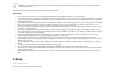
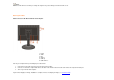
Adjusting Viewing Angle • • • For optimal viewing it is recommended to look at the full face of the monitor, then adjust the monitor's angle to your own preference. Hold the stand so you do not topple the monitor when you change the monitor's angle. You are able to adjust the monitor's angle from -5°to 15°.
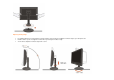
NOTE: Do not touch the LCD screen when you change the angle. It may cause damage or break the LCD screen. Attaching the Cables Cable Connections On Back of Monitor and Computer 1. Power 2. Audio 3. DVI 4. Analog 5. USB up 6. USB down x 3 Turn off your computer before performing the procedure below. 1. 2. 3. Connect the power cable to the AC port on the back of the monitor. Connect one end of the 15-pin D-Sub cable to the back of the monitor and connect the other end to the computer's D-Sub port.
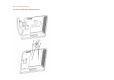
Attaching Wall Mounting Arm Preparing to Install An Optional Wall Mounting Arm
This monitor can be attached to a wall mounting arm you purchase separately. Disconnect power before this procedure. Follow these steps: 1. 2. 3. 4. 5. Remove the base. Follow the manufacturer's instructions to assemble the wall mounting arm. Place the wall mounting arm onto the back of the monitor. Line up the holes of the arm with the holes in the back of the monitor. Insert the 4 screws into the holes and tighten. Reconnect the cables.
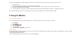
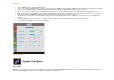
1 2 3 4 5 6 7 Eco Mode / Up Auto (Exit) / Left Menu / Right Volume Power on/off Camera microphone Operation Steps 1) Press the MENU-button ( ) to activate the OSD window. 2) Press or to navigate through the functions. Once the desired function is highlighted, press the MENU-button to activate sub-menu . Once the desired function is highlighted, press MENU-button to activate it. 3) Press or to change the settings of the selected function. Press or to select another function in sub-menu .
OSD Settings • • • • • • • Press the MENU-button to activate the OSD window. Press+ or - to navigate through the functions. Once the desired function is highlighted, press the MENU-buttonto activate it.If the function selected has a sub-menu, press or again to navigate through the sub-menu functions.Once the desired function is highlighted, press MENU-button to activate it. Press+ or - to change the settings of the selected function. To exit and save, select the exit function.
DCC: Dynamic color control ICM: Intelligent color management 1) How to use Color Boost? YCM adjustment: In addition to the basic R (red), G (green), B (blue) color adjustments, Color Boost has added Y (yellow), C (cyanine), and M (magenta) for more color fine-tuning options. YCM adjustments are in the third icon labeled "Color Temperature "in the OSD menu. When adjusting YCM values, RGB values will also be changed automatically due to the color correlation between RGB and YCM.
Full Enhance: When "Full Enhance" is turned on, the color saturation of the entire screen is fully enriched, thus all colors become more vibrant. Nature Skin: When "Natural Skin" is turned on, the red and yellow colors are enriched automatically, thus presents human skin with more natural and truer colors. "Natural Skin" setting is ideal for viewing human portrait and detailed skin texture.
Green Field: When "Green Field" is turned on, the green color is enriched so that football field and mountain landscape would look more natural and fresh. “Green Field” setting is ideal for watching mountain scenery and outdoor sports. Sky Blue: When"Sky Blue" is turned on, the color blue is being fine-tuned so that the sky or ocean landscape will look more vivid and in-depth. "Sky Blue" setting is ideal for viewing sky and ocean images.
Auto Detect: Demo: When “Auto Detect” is turned on, every pigment will be detected and self-adjusted to render a lively picture. Screen divided into two for demonstration purposes. 2) How to use Picture Boost? Users can change the color settings of a self-selected zone on the screen. The size and position of the selected zone can also be adjusted. "Picture Boost" is located in the fifth icon labeled "Picture Boost" in the OSD menu. Turn on "Bright Frame" to select a zone on the screen to be enhanced.
Disclaimer: DCB aftereffects are subject to the resolution and quality of the display content, hence may look different than the above illustrations. DCR Adjustment What is DCR? Dynamic Contrast Ratio (DCR) auto adjusts the brightness of the screen so users can see the darker areas of the displayed content in more depths. By increasing the darkness of the dark areas and the brightness of the bright areas, contrast ratio is uplifted to exceed 2000:1.
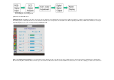
DCR Demos: Disclaimer: DCR aftereffects are subject to the resolution and quality of the display content, hence may look different than the above illustrations. Function Control Illustration Luminance Brightness Contrast Eco mode Adjust Range 0-100 0-100 Standard Text Description Backlight Adjustment Contrast from Digital-register.
Gamma DCR Image Setup Clock Focus H.Position V.Position Color Temp.
OSD Setup H.Position V.
9. Click on the 'Open' button, then click on the 'OK' button. 10. Select your monitor model and click on the 'Next' button. 11. Click on the 'Finish' button then the 'Close' button. If you can see the 'Digital Signature Not Found' window, click on the 'Yes' button. Windows ME 1. Start Windows® Me 2. Click on the 'Start' button, point to 'Settings', and then click on 'Control Panel'. 3. Double click on the 'Display' Icon. 4. Select the 'Settings' tab then click on 'Advanced...'. 5.
13. Click on the 'Finish' button then the 'Close' button. 14. Click on the 'OK' button and then the 'OK' button again to close the Display_Properties dialog box. Windows Vista 1. Start Windows® Vista 2. Click the Start button; select and click on 'Control Panel'. 3. Select and click on 'Hardware and Sound' 4. Choose 'Device Manager' and Click on 'Update device drivers'. 5. Select 'Monitor' and then right click on 'Generic PnP Monitor'. 6. Click on 'Update Driver Software'. 7.
• • • • The Computer Video Card should be snugly seated in its slot. Make sure the monitor's video cable is properly connected to the computer. Inspect the monitor's video cable and make sure none of the pins are bent. Make sure your computer is operational by hitting the CAPS LOCK key on the keyboard while observing the CAPS LOCK LED. The LED should either turn ON or OFF after hitting the CAPS LOCK key. • • Inspect the monitor's video cable and make sure that none of the pins arebent.
Power Consumption Speakers Connector Type Signal Cable Type Dimensions & Weight: Height (with base) Physical Characteristics Width Depth Weight (monitor only) Weight (with packaging) Temperature: Operating Non-Operating Humidity: Environmental Operating Non-Operating Altitude: Operating Non-Operating Active < 49W Standby < 1W 2 x 1.5w 15-pin Mini D-Sub & DVI-D Detachable 505.2 mm 442.3 mm 280.1 mm 5.58 kg 7.
1280x1024 1680x1050 WSXGA 79.976 65.29 75 60 Pin Assignments Pin Number 15-Pin Side of the Signal Cable 1 2 3 4 5 6 7 8 9 10 11 12 13 14 15 Pin No. 1 2 3 4 5 Video-Red Video-Green Video-Blue N.C. Ground GND-R GND-G GND-B +5V Detect Cable N.C. DDC-Serial data H-sync V-sync DDC-Serial clock Signal Name TMDS Data 2TMDS Data 2+ TMDS Data 2/4 Shield TMDS Data 4TMDS Data 4+ Pin No. 9 10 11 12 13 Signal Name TMDS Data 1TMDS Data 1+ TMDS Data 1/3 Shield TMDS Data 3TMDS Data 3+ Pin No.
6 7 8 DDC Clock DDC Data N.C. 14 15 16 +5V Power Ground(for+5V) Hot Plug Detect 22 23 24 TMDS Clock Shield TMDS Clock + TMDS Clock - Plug and Play Plug & Play DDC2B Feature This monitor is equipped with VESA DDC2B capabilities according to the VESA DDC STANDARD. It allows the monitor to inform the host system of its identity and, depending on the level of DDC used, communicate additional information about its display capabilities. 2 The DDC2B is a bi-directional data channel based on the I C protocol.
AOC International (Europe) GmbH will pay the return shipping charges within one of the countries specified within this warranty statement. AOC International (Europe) GmbH is not responsible for any costs associated with the transportation of product across international borders. This includes the international border within the European Union.