41G2001-615-1A 英文
TABLE OF CONTENTS FOR YOUR SAFETY -------------------------------------------------- 1 SAFETY PRECAUTIONS -------------------------------------- 2 SPECIAL NOTES ON LCD MONITORS ------------------- 3 BEFORE YOU OPERATE THE MONITOR --------------------FEATURES -------------------------------------------------------PACKING LIST --------------------------------------------------INSTALLATION INSTRUCTIONS --------------------------CONTROLS AND CONNECTORS -------------------------ADJUSTING THE VIEWING ANGLE ------
Before operating the monitor, please read this manual thoroughly. This manual should be retained for future reference. FCC Class B Radio Frequency Interference Statement WARNING: (FOR FCC CERTIFIED MODELS) NOTE: This equipment has been tested and found to comply with the limits for a Class B digital device, pursuant to Part 15 of the FCC Rules. These limits are designed to provide reasonable protection against harmful interference in a residential installation.
PRECAUTIONS z Do not use the monitor near water, e.g. near a bathtub, washbowl, kitchen sink, laundry tub, swimming pool or in a wet basement. z Do not place the monitor on an unstable cart, stand, or table. If the monitor falls, it can injure a person and cause serious damage to the appliance. Use only a cart or stand recommended by the manufacturer or sold with the monitor. If you mount the monitor on a wall or shelf, use a mounting kit approved by the manufacturer and follow the kit instructions.
SPECIAL NOTES ON LCD MONITORS The following symptoms are normal with LCD monitor and do not indicate a problem. NOTES • Due to the nature of the fluorescent light, the screen may flicker during • • • initial use. Turn off the Power Switch and then turn it on again to make sure the flicker disappears. You may find slightly uneven brightness on the screen depending on the desktop pattern you use.
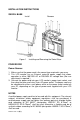
INSTALLATION INSTRUCTIONS SWIVEL BASE Install Figure 1 Remove Installing and Removing the Swivel Base POWERCORD Power Source: 1. Make sure that the power cord is the correct type required in your area. 2. This LCD monitor has an External universal power supply that allows operation in either 100/120V AC or 220/240V AC voltage area (No user adjustment is required.) 3. Connect the power cord into your LCD monitor’s power input socket, and then plug the other end into a 3-pin AC power outlet.
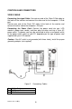
CONTROLS AND CONNECTORS VIDEO CABLE Connecting the signal Cable: Connect one end of the 15-pin D-Sub cable to the back of the monitor and connect the other end to the computer’s D-Sub port. Connect one end of the 24-pin DVI cable to the back of the monitor and connect the other end to the computer’s DVI port. Connecting the Power Cord: Connect the power cord into your LCD monitor’s power input socket, and then plug the other end into a 3-pin AC power outlet.
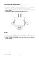
ADJUSTING THE VIEWING ANGLE • For optimal viewing it is recommended to look at the full face of the monitor, then adjust the monitor’s angle to your own preference. • Hold the stand so you do not topple the monitor when you change the monitor’s angle. • You are able to adjust the monitor’s angle from -5° to 25°. Figure 3 NOTES • Do not touch the LCD screen when you change the angle. It may cause damage or break the LCD screen.
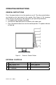
OPERATING INSTRUCTIONS GENERAL INSTRUCTIONS Press the power button to turn the monitor on or off. The other control buttons are located on the front panel of the monitor (See Figure 4). By changing these settings, the picture can be adjusted to your personal preferences. • The power cord should be connected. • Connect the video cable from the monitor to the video card. • Press the power button to turn on the monitor position. The power indicator will light up.
FRONT PANEL CONTROL • Power Button / Power Indicator: Press this button to turn the monitor ON or OFF. Blue — Power On mode. Orange — Off mode. • MENU / ENTER : Activate OSD menu when OSD is OFF or activate/de-activate adjustment function when OSD is ON or Exit OSD menu when in Volume Adjust OSD status. • Auto Adjust button / Exit: 1. 2. When OSD menu is in active status, this button will act as EXIT-KEY (EXIT OSD menu).
HOW TO ADJUST A SETTING 1. Press the MENU-button to activate the OSD window. 2. Press < or > to navigate through the functions. Once the desired function is highlighted, press the MENU-button to activate it. If the function selected has a sub-menu, press < or > again to navigate through the submenu functions. Once the desired function is highlighted, press MENUbutton to activate it. 3. Press < or > to change the settings of the selected function. 4. To exit and save, select the exit function.
ADJUSTING THE PICTURE The descriptions for function control LEDS Main Main Sub Menu Sub Menu Menu Item Menu Item Icon Icon Lumina nce Image Setup Contrast from Digital- Recall Cool register. Contrast Value Brightness Backlight Adjustment Recall Cool Brightness Value Adjust Picture Phase Do Auto Config to reduce HorizontalLine noise Adjust picture Clock Do Auto Config to reduce VerticalLine noise. Adjust the horizontal Do Auto Config position of the picture.
OSD Setup H. Position Adjust the horizontal 50 position of the OSD. V. Position 50 Adjust the verticalposition of the OSD. Adjust the OSD 10 timeout. OSD Timeout Langua ge Informat ion Reset Exit 41G2001-615-1A 英文 English N/A Deutsch N/A Français N/A Español N/A Italiano N/A 简体中文 N/A Information N/A Yes N/A No N/A N/A N/A Set OSD display language to English. Set OSD display language to German. Set OSD display language to French. Set OSD display language to Spain.
PLUG AND PLAY Plug & Play DDC2B Feature This monitor is equipped with VESA DDC2B capabilities according to the VESA DDC STANDARD. It allows the monitor to inform the host system of its identity and, depending on the level of DDC used, communicate additional information about its display capabilities. The DDC2B is a bidirectional data channel based on the I²C protocol. The host can request EDID information over the DDC2B channel.
TECHNICAL SUPPORT (FAQ) Problem & Question Power LED is not on No Plug & Play Picture is fuzzy Picture bounces or a wave pattern is present in the picture The power LED is ON but there’s no video or no picture.
Screen image is not centered or *Adjust pixel frequency (CLOCK) and sized properly. FOCUS or press hot-key (AUTO). Picture has color defects *Adjust RGB color or select color (white does not look white) temperature. Horizontal or vertical *Use win 95/98 shut-down mode Adjust disturbances on the screen CLOCK and FOCUS or perform hot- key (AUTO-key). CLOCK (pixel frequency) controls the number of pixels scanned by one horizontal sweep.
ERROR MESSAGE & POSSIBLE SOLUTION CABLE NOT CONNECTED : 1. Check that the signal-cable is properly connected , If the connector is loose, tighten the connector’s screws. 2. Check the signal-cable’s connection pins for damage. INPUT NOT SUPPORTED : Your computer has been set to unsuitable display mode ,set the computer to display mode given in the following table (See page 19).
APPENDIX SPECIFICATIONS Driving system TFT Color LCD LCD Panel Size 51cm(20") Pixel pitch 0.255mm( H )x 0.255mm( V ) Viewable angle 170° (H) 170° (V) Video R,G,B Analog Interface Digital interface H-Frequency 30KHz – 80Hz V-Frequency 55-75Hz Display Colors 16.7M Colors Dot Clock 162 MHz Max. Resolution 1600 x 1200 @ 60Hz Plug & Play VESA DDC1/2BTM Power Consumption ON Mode OFF Mode ≤55 W ≤2W Input Connector D-Sub 15pin DVI 24pin Input Video Signal Analog:0.
• • • • • • • • • • • • • • • • • • • • • • Switch External Controls: Power Button Contrast Brightness Focus Clock H.Position V.
Preset Display Modes STANDARD IBM DOS VGA RESOLUTION HORIZONTAL FREQUENCY(KHZ) VERTICAL FREQUENCY(HZ) 720 × 400 31.47 70.0 640 × 480 31.47 60.0 640 × 480 37.50 75.0 800 × 600 37.879 60.0 800 × 600 46.875 75.00 1024 × 768 48.363 60.0 1024 × 768 56.476 70.0 1024 x 768 60.02 75.0 1024 x 768 48.780 60.0 1024 x 768 60.241 75.0 1280 × 1024 64.00 60.0 1280 × 1024 80.00 75.0 1600 x 1200 75.00 60.
CONNECTOR PIN ASSIGNMENT 1 5 6 10 11 15 15 - Pin Color Display Signal Cable PIN NO. 1. 2. 3. 4. ` 6. 7. 8. DESCRIPTION PI N NO. DESCRIPTION 9. 10. 11. 12. 13. 14. 15. +5V Detect Cable NC DDC-Serial data H-sync V-sync DDC-Serial clock Video-Red Video-Green Video-Blue NC Ground GND-R GND-G GND-B 24 - Pin Color Display Signal Cable PIN NO. DESCRIPTION PI N NO. 1. 2. 3. TMDS Data 2TMDS Data 2+ TMDS Data 2/4 Shield TMDS Data 4TMDS Data 4+ DDC Clock DDC Data 13. 14. 15.
41G2001-615-1A 英文 21