
Install Instructions


7
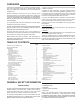
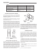
AUTOMATIC GAS SHUTOFF CONTROL
The automatic gas shutoff control, g. 1, is an automatic safety
device which activates at a water temperature of approximately
195
0
F (90.5°C). This limits the water outlet temperature to a
maximum of 200
0
F (87.7°C).
The device is wired in series with the gas valve. The control
will automatically reset when the water temperature cools to
approximately 190
o
F (87.7°C).
Should the automatic gas shutoff control activate during a
heating cycle, the heater’s gas valve will close; extinguishing the
main burners. The pilot burner will also be extinguished. The
circulating pump will continue operating as long as the storage
tank thermostat continues to “call for heat”. When the water
temperature in the heater drops to 180
0
F (82.2°C) or below the
control module will begin an ignition cycle which will relight the
pilot burner and main burners. Re-ignition of the main burners
will occur if the storage tank thermostat continues to call for
heat. Otherwise, the normal operating cycle will resume on the
thermostat’s next call for heat.
AUTOMATIC GAS SHUTOFF CONTROL
FIGURE 1
PROTECTOR SWITCH
(Coil High Limit)
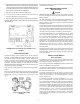
This heater is equipped with a manually reset protector switch,
Figure 2, located under the small cover on the side of the jacket.
This device provides positive shutdown of the heater in the event
of heater or system malfunction. Should the surface temperature
of the copper tubing heat exchanger reach 250
0
F (121.1°C), the
protector switch will activate. The gas valve will close, and the
pilot and main burners will be extinguished. To resume heater
operation, the protector switch must be manually reset (remove
the protector switch cover and push the reset button) after the coil
surface temperature cools to less than 200
0
F(93.3°C).
FIGURE 2
DO NOT RESET THIS SWITCH WITHOUT PERFORMING THE
SYSTEM CHECKS OUTLINED UNDER PROTECTOR SWITCH
IN THE SERVICE INFORMATION SECTION. ALSO, SEE CHART
ONE UNDER THE CHECKOUT SECTION. IF NECESSARY,
CALL A QUALIFIED SERVICE AGENT. Once the cause of the
protector switch activation has been determined and corrected,
it will be necessary to restart the heater following the LIGHTING
AND OPERATING instructions.
THERMAL BALANCER
The thermal balancer (standard on Models HW-200M and
HW-225M, optional on Models HW-120M and HW-160M) is
a delay relay used only on Cer-Temp 80 Recovery systems.
It gives immediate pump start but delay of pump shutoff for
approximately 2 minutes. Residual heat in the heat exchanger
is then recovered after shutdown. This improves efficiency
and balances heater temperature with tank temperature at
shutdown.
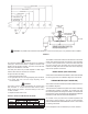
INTERMITTENT IGNITION CONTROL MODULE
The Honeywell control module contain the electronic components
of the system and also serve as a central wiring system for the
controls mounted on the heater. The control module performs the
following functions:
1. Checks for safe-start by sensing for a ame or false ame
condition on start-up.
2. Generates a potential of 15,000 volts for spark ignition of the
pilot burner.
3. Turns on or off power to the pilot valve.
FEATURES
Control Device Factory Setting Field Adjustment
195
0
F (90.5°C) cut out temp.
Heater Automatic Gas Shutoff Control Fixed 190
0
F (87.7°C) cut in temp. Non-adjustable
250
0
F (121°C) cut out temp.
Heater Protector Switch Fixed 200
0
F (93.3°C) cut in temp. Non-adjustable
Tank Temperature Control Field Supplied and Installed Adjust to Requirements
Safety Flow Switch See Table 1 Field Adjustable
TABLE 4.