
Install Instructions


17
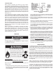
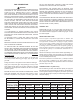
ELECTRICAL WIRING DIAGRAMS FOR THE HW-120M, 160M, 200M AND 225M WATER HEATERS
I.I.D. SYSTEM
FIGURE 10
A minimum gas supply pressure of 4.5” W.C. (1.12kPa) for
natural gas and 11” W.C. (2.74kPa) for propane gas is required
for purposes of input adjustment.
ELECTRICAL INFORMATION
ALL ELECTRICAL WORK MUST BE INSTALLED IN
ACCORDANCE WITH THE NATIONAL ELECTRICAL CODE IN
THE UNITED STATES.
The electrical connections must be made so that both the
circulator and intermittent ignition device operate simultaneously
when the storage tank temperature control calls for heat.
The water heater, when installed, must be electrically grounded
in accordance with local codes or, in the absence of local codes,
in the United States with the NATIONAL ELECTRICAL CODE,
ANSI/NFPA 70.
A screw is provided in the heater junction box for a ground
connection.
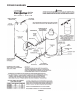
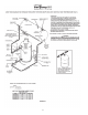
All piping diagrams include an electrical wiring diagram to assist
the installer in properly wiring of the additional components
required to assure correct system operation.
Figures 10 show the heater mounted controls as they are wired
when the heater leaves the factory. Using the individual wiring
diagrams on the installation diagrams, the installer connects
his wiring to terminals in the heater(s) mounted junction box
as shown.
All wiring should be done such that the heater(s) will operate in
the following manner:
1. When the tank temperature control calls for heat:
• The circulating pump starts to operate. Once the safety ow
switch contacts close, intermittent ignition device is powered
and sequence through steps as described for I.I.D. Control
Module on Page 6.
2. When the tank temperature control is satised:
• The main burners should stop ring, but the circulating pump
should continue to operate for about 2 minutes when equipped
with a thermal balancer.
3. When the automatic gas shutoff control or coil protector switch
operate (break electric circuit):
• The main burners should stop ring. Circulating pump should
continue to operate.