
Install Instructions


11
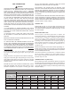
CONFINED SPACE
When drawing combustion and dilution air from inside a
conventionally constructed building to a conned space, such a
space shall be provided with two permanent openings, ONE IN OR
WITHIN 12 INCHES (30.5cm) OF THE ENCLOSURE TOP AND
ONE IN OR WITHIN 12 INCHES (30.5cm) OF THE ENCLOSURE
BOTTOM. Each opening shall have a free area of at least one
square inch per 1000 Btuh (2,225mm
2
/Kw) of the total input of all
appliances in the enclosure, but not less than 100 square inches
(645 square cm).
If the conned space is within a building of tight construction,
air for combustion, ventilation and draft hood dilution must be
obtained from outdoors. When directly communicating with the
outdoors or communicating with the outdoors through vertical
ducts, two permanent openings, located in the above manner,
shall be provided. Each opening shall have a free area of not less
than one square inch per 4000 Btuh (8,900mm
2
/Kw) of the total
input of all appliances in the enclosure. If horizontal ducts are
used, each opening shall have a free area of not less than one
square inch per 2000 Btuh (4,450mm
2
/Kw) of the total input of all
appliances in the enclosure. For Canadian installations consult
CAN/CGA B149.
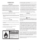
Where an exhaust fan is installed in the same room with a
heater, sufcient openings for air must be provided in the walls.
UNDERSIZED OPENINGS WILL CAUSE AIR TO BE DRAWN
INTO THE ROOM THROUGH THE CHIMNEY, CAUSING
POOR COMBUSTION. SOOTING MAY RESULT AND RISK OF
ASPHYXIATION WILL OCCUR.
VENTING
In the United States:
Vent sizing, installation and termination shall be in accordance with
current edition of the NATIONAL FUEL GAS CODE. ANSI Z223.1.
Remove all soot or other obstructions from chimney which will
retard free draft.
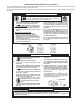
1. Install and size the vent pipe as necessary. The connection from
the heater to the chimney should be run full size and should
have a minimum pitch upward to the chimney of one quarter
inch per foot length.
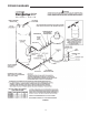
PROPER VENT PIPE INSTALLATION
FIGURE 6
Do not install without draft hood and do not install any damper
in ueway. Be sure that the vent pipe does not extend beyond
the inside wall of the chimney.
2. Where a continuous or intermittent back draft is found to exist,
the cause must be determined and corrected. A special vent
cap may be required.
FAILURE TO CORRECT BACK DRAFTS MAY CAUSE AIR
CONTAMINATION AND UNSAFE CONDITIONS.
• If the back draft cannot be corrected by the normal methods
or if a suitable draft cannot be obtained, a blower type ue
gas exhauster must be employed to assure proper venting and
correct combustion.
3. Do not connect the heater to a common ue or chimney with
solid fuel burning equipment. This practice is prohibited by
many local building codes as is the practice of venting gas red
equipment to the duct work of ventilation systems.
• Where a separate vent connection is not available and the vent
pipe from the heater must be connected to a common ue with an
oil burning furnace, the vent pipe should enter the common ue
or chimney at a point above the ue pipe from oil furnace.
4. Where two or more appliances vent into a common vent
connector or manifold, the area of the common vent should at
least equal the area of the largest ue or vent connector plus
50% of the areas of the additional draft hood outlets.
5. Refer to the National Fuel Gas Code for information pertaining
to multiple heater venting. The ASHRAE HVAC SYSTEMS &
EQUIPMENT HANDBOOK, as well as many manufacturers’
gas vent and chimney sizing handbooks contain information
on multiple heater manifold venting.
RELIEF VALVE
An ASME-rated pressure relief valve (Supplied) must be installed
in the hot water outlet line as near to the heater as possible. This
pressure relief valve is rated in accordance with and complies with
the current edition of the ANSI/ASME Boiler and Pressure Vessel
Code, Section IV.
A CSA design-certied and ASME-rated temperature and pressure
relief valve (Not Supplied) must be installed on each and every water
storage tank. This relief valve shall comply with the Standard for
Relief Valves for Hot Water Supply systems, “ANSI Z21.22 current
edition”. This relief valve should have a temperature rating of 210°F
(98.8°C), a pressure rating not exceeding the lowest rated working
pressure of any system component and a discharge capacity
exceeding the total input of the water heaters supplying water to
the storage tank.
Select a relief valve with a discharge capacity exceeding the
maximum heater input rating and a pressure rating not exceeding
the working pressure shown on the rating plate of the heater.
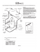
Locate the T & P relief valve in the top of the tank, or in the side
of the tank on centerline within the upper 6 inches from the top of
the tank. See installation diagrams. Tapping shall be threaded
in accordance with the latest version of the Standard for Pipe
Threads, General Purpose (inch), ANSI/ASME B1.20.1. Mark
location with a Class III label.