
Install Instructions


10
INSTALLATION INSTRUCTIONS
IMPORTANT
Strict adherence to installation wiring diagrams shown in this manual
is required to prevent constant pump operation when the system
temperature control is satised, otherwise the warranty is void as
stipulated under item 2a (6) of the LIMITED WARRANTY.
REQUIRED ABILITY
INSTALLATION OR SERVICE OF THIS WATER HEATER
REQUIRES ABILITY EQUIVALENT TO THAT OF A LICENSED
TRADESMAN IN THE FIELD INVOLVED. PLUMBING, AIR SUPPLY,
VENTING, GAS SUPPLY AND ELECTRICAL WORK ARE REQUIRED.
LOCATION
When installing the heater, consideration must be given to proper
location. Location selected should be as close to the stack or
chimney as practicable with adequate air supply, and as centralized
with piping system as possible.
THE HEATER SHOULD NOT BE LOCATED IN AN AREA WHERE
IT WILL BE SUBJECT TO FREEZING.
LOCATE IT NEAR A FLOOR DRAIN. THE HEATER SHOULD BE
LOCATED IN AN AREA WHERE LEAKAGE FROM THE HEATER OR
CONNECTIONS WILL NOT RESULT IN DAMAGE TO THE ADJACENT
AREA OR TO LOWER FLOORS OF THE STRUCTURE.
WHEN SUCH LOCATIONS CANNOT BE AVOIDED, A SUITABLE
DRAIN PAN SHOULD BE INSTALLED UNDER THE HEATER.
Such pans should be fabricated with sides at least 2” (50.8mm)
deep, with length and width at least 2” (50.8mm) greater than the
diameter of the heater and must be piped to an adequate drain.
The pan must not restrict combustion air ow.
Should the heater be installed in a garage, the heater must be located, or
protected, so it is not subject to physical damage by a moving vehicle.
For water heater installation in locations with elevations above
2,000 feet (610M), refer to HIGH ALTITUDE INSTALLATIONS
section of this manual for input reduction procedure.
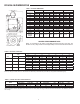
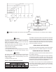
INSTALLATION CLEARANCES
These units are approved for installation in an alcove having
minimum clearances from combustible construction of 44”
(1,118mm) from top of the jacket, 6” (152.4mm) from sides, and
6” (152.4mm) from rear and vent connections.
All models may be installed on combustible ooring.
DO NOT INSTALL THIS WATER HEATER DIRECTLY ON A
CARPETED FLOOR. A FIRE HAZARD MAY RESULT. Instead the
water heater must be placed on a metal or wood panel extending
beyond
the full width and depth by at least 3 inches (76.2mm) in any
direction. If the heater is installed in a carpeted alcove, the entire oor
shall
be covered by the panel. Also, see the DRAIN REQUIREMENTS.
It is recommended that at least 24” (610mm) be provided on the left
side and front of the unit for accessibility and proper servicing. In a
utility room installation, the door shall be wide enough to allow the
heater to enter or to permit the replacement of another appliance.
LEVELLING
Each unit should be checked after installation to be certain that
it is level.
If the unit is not level, obtain and insert metal shims under the
base ring of the unit to correct this condition.
AIR REQUIREMENTS
UNCONFINED SPACE
In buildings of conventional frame, brick, or stone construction,
unconned spaces may provide adequate air for combustion,
ventilation and draft hood dilution.
If the unconned space is within a building of tight construction
(buildings using the following construction: weather stripping,
heavy insulation, caulking, vapor barrier, etc.), air for combustion,
ventilation, and draft hood dilution must be obtained from outdoors.
The installation instructions for conned spaces in tightly constructed
buildings must be followed to ensure adequate air supply.