
User's Manual

AnyDATA.NET Inc. AnyTime AnyPlace Any Wireless Data Solution
TM
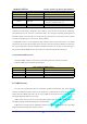
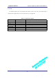
4.7.3 Ringer (Pin74)
The Ringer pin provides the output to drive the sound transducer on the host. It alerts the user of a
voice call event and outputs key tones if the keypad is connected.
The DTG2000-Dual V2.0 module includes Ringer Driver and drives Buzzer directly.
Table 4-8 Ringer/Buzzer Driver Output Spec.
PARAMETER
TEST CONDITION TYPICAL VALUE
Drive Frequency
Max 8kHz
Load Current
R_load=10 ohm Min 300mA
Load Resistance
Typ 10 ohm
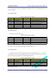
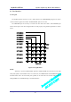
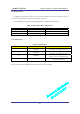
4.7.4 LED Interface
Table 4-9 LED interface
PIN NUMBER
USE REMARK
34
Idle LED
High Enable, High indicates
“The device is in CDMA service area”
35
Busy LED
High Enable, High indicates
“The device is in CDMA Traffic state”
67
SMS LED
High Enable High indicates
“The device has received SMS message
72
Power On LED
High Enable High indicates
“The device is turned on”
Above pins can not drive LED directly. Must use driver ICs to drive LEDs
All Rights Reserved.
AD-2001-06-28 Ver 1.1
-28-