
User's Manual

AnyDATA.NET Inc. AnyTime AnyPlace Any Wireless Data Solution
TM
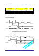
4.2.2 Supply Input to BATT_INT (Pin 88 and Pin 90)
If the customers need to get their device to operate in a very low sleep current mode, supplying the
voltage input to BATT_INT (Pin 88 and 90) is recommended.
When the input voltage from +3.4V to +4.3V is supplied to BATT_INT(Pin88 and 90), DTG2000-Dual
V2.0 won’t automatically start its power-on process without low assertion of POWER_ON (Pin 30). To
power the module on, first apply VCC to BATT_INT and have POWER_ON (Pin30) stay low for more
than 500 msec and less than 2 sec.
POWER_ON (Pin 30) needs to be externally pulled up to 3V to 3.6V thru 100kohm resistor.
To power off the module, have POWER_ON(Pin 30) stay low for more than 2sec and less than 4sec and
then the voltage in BATT_INT may or may not be removed.
If Vcc is supplied thru a regulator to BATT_INT(Pin88 and 90), using a regulator with an enable pin is
highly recommended so that the customer can shut off the power to the module using the enable pin if
software lock-up symptoms are found. If the modem is locked up, low assertion of POWER_ON(Pin 30)
won’t power on or off the module or Pin 31(Ext_Reset) may not work.
If Vcc is supplied directly from a battery, having a FET between the output of a battery and input of
DTG2000-Dual V2.0 is recommended that the customer can shut off the Vcc to DTG2000-Dual V2.0
using the FET as a reset method..
4.3 CODEC Interface
With the integrated microphone and earpiece amplifier including CODEC, the DTG2000-Dual V2.0
module interfaces directly, either differential or single-ended, to the microphone and earpiece.
The audio features in the module are
- Two microphone inputs
- Two earphone outputs and one auxiliary audio output.
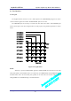
4.3.1 Internal CODEC Interface
The module contains analog audio interface circuitry. The contained audio interface supports all of the
required conversation and amplification stages for the audio front end.
The audio interface includes the amplification stages for both the microphone and earphone.
The EAR10 and MIC1P are typically used for the handset microphone,
The EAR_JACK+ and MIC2P are typically used for the ear-jack.
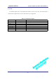
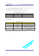
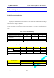
Table 4-1 Analog Audio Pinouts
All Rights Reserved.
AD-2001-06-28 Ver 1.1
-21-
NAME
DESCRIPTION CHARACTERISTIC
MIC2P
Mic Jack Input Analog Input (Pin No. 83, for Ear-Mic Jack) *
EAR_DET1 EAR/MIC Set Detect Logic Input (Pin No. 78) **
EAR_JACK+ Earphone Output Analog Output (Pin No. 79 for Ear-Mic Jack)