Safety Instructions Always fallow the safety instructions during assembly and usage; to avoid any unnecessary damage to the 30 printer or individual injury Please contact our customer service first if you have any issue after reeving the products. Be cautious when using the scraper. Never direct the scraper towards your hands. Incas of emergency, please immediately cut off the power of ANY CUBIC 3D printer and contact the technical support. CUBICAL teleprinter includes moving parts that can cause injury.
Contents 1. Technical Specification 2. Packing List 3. Product Overview 4. Menu Directory 5. Assembly and Leveling Instructions 6. First Print Instructions anglicizing Software 8.
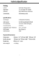
Technical Specification Recommended Printing Parameters Layer Thickness Normal Exposure Time Off Time Bottom Exposure Time Bottom Layers Z Lift Distance Z Lift Speed Z Retract Speed Anti-alias 0.05 mm 2s 0.
Packing List Print platform Resin vat 1°05 1P(S ¢ =] USE | | Td Photon Mono us memory | cancers ans plus a 1% Shs Assembly Mask 1PCsS Gloves 3 Pairs Funnel PCS instruction plus This paper # iid .
Product Overview Z lead screw Platform securing Knob gl Platform bracket Printing platform Vat retaining screw Resin vat USB port Touch screen Power switch Sticker Power port
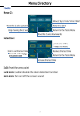
Menu Directory Home menu 0 : OF Priority Oyster Move 2 ae Home menu Lent : Enter the Print Menu ; Lh : Enter the System Menu OF Enter the Tools Menu
Menu Directory Print File List: BE ar Page up Page down Return to the Home Menu Click Files Delete the current file click-to start printing Return to the Print Menu System Language: Change Service: Official website Return to the Shyster Menu Information: Product system System version Product ID Rel Urn to the System Menu
Menu Directory Tools Move Z: Ge = Lom Move Z by Move the Z axis upwards Return'to Erg Stop moving the Z axis Return to the Tools Menu Detection: Select one of the images to detect Click to set the test time Reduce the test time Test LED and LCD for | the preset time Return to the Tools Menu | Increase the test time Z=0: Reset the zero point Lock icon: Enable/disable the door detection function Horn icon: Turn on/off the screen sound
Assembly and Leveling Instructions 1.Unpack the machine and take out the accessories. Then plug in the power cord and turn-on the printer. 2. Click “Tools” = "Move on the touch screen to raise Z axis.
Assembly and Leveling Instructions 3. Unscrew four screws on the platform, 4. Install the printing platform. 5. Place a leveling paper on the curing screen. Then click the “Tools” — “Move Z" —" "on the color screen. Wait for the Z axis to descent and then it will stop automatically.
Assembly and Leveling Instructions 6. Finger press onto of the platform gently, to lest fit evenly on the curing screen. Then tighten the four screws on the platform. 7. Lastly, click “Tools"= “Z=0" on the touch screen, and then click “Enter” on the pop-up window. Till now, the leveling process is finished. Click “Enter” again on the pop-up window and pull out A4 paper. 8, Testing UV light: Click "Tools”— “Detection”, select a image and the test time, and then click “Next” on the screen as shown below.
Assembly and Leveling Instructions @ lick to set the exposure time in Hellion Select the detection result in the first box 9. Install the resin vat.
First Print Instructions To Print Insert the USB memory (the test file“ TEST. pwmio™ has been saved in it) into the USB port. Then wear masks and gloves, slowly pour the resin into the vat and the resin cannot exceed the maximum scale in the vat. After that, cover the lid and the side with sticker needs to face backward. Take off the gloves, select the "Testimony" test file-and start printing. (The printing time on the screen is for reference only, we make no guarantee that it is the actual printing time.
First Print Instructions 2. Door detection function Door detection function is disabled by default. If this function is enabled, the printer can detect whether the lid is on-or not. If the lid is removed, the printing will be paused. And the printing will resume if put back the lid. Click the lock icon on “Tools” interface to enable/disable this function. After click, the lock icon is locked and the i function is enabled.
Slicing Software (1) Open, save, undo and redo. @) Model mirror, hollow and infill, punching, text paste and split model explained in the following parts. @ Click to switch the preset view. @ Switch between slice/machine settings and support settings. (& Drag the slider to preview each layer of the model: © “3D model preview. Click to slice. ® Move, rotate, scale and layout. ©) Click to switch to the Configuration Mode. 3.
Slicing Software (2) View Changing @ View changing by mouse * the mouse wheel. + Position change: left click the platform; hold on and move the mouse. + Change view angle: right click the platform, hold on and move the mouse. @ View changing by interface controls: click the-arrow-can change the viewing angle by 90°in its direction.
Slicing Software (3) Model Changing Move selected: click “move” icon, input a number or manipulate the controls can move the model. You also can center or reset the model. Rotate selected: click “rotate icon, input a number or manipulate the controls can rotate the model. You also can reset the model. Scale selected: click “scale” icon; input a number or percentage or manipulate the controls can scale the model. You also can set the model to its maximum size.
Slicing Software @ Model rotating: Choose a larger facet as the ground. fitting platform, which can improve print success rate. Rotate Check off Click or the larger bottom of the model. @ Model scaling After setting the model to the maximum size, center it to avoid the model exceeding the print range.
Slicing Software ® Center the model: Fix Maximum TS Le Cl Select the model and click "Duplicate", then an identical model will be duplicated. (Those models may overlap) For multiple models, click ’X Side" or "Y Side", the models can be aligned orY direction.
Slicing Software (4) Hollow And Fill in some cases, you don't need the model to be completely solid. Before you start slicing a model, you can hollow to reduce resin consumption. a Please check and choose the most suitable parameters for hollowing and infilling to fit your requirement.
Slicing Software : Hollow thickness: 1mm Hollow thickness: 3mm The model name: MIA The.author.of the model: Fa bio Tanisha You may drag the slider to see the internal structure of the model after hollowing.
Slicing Software Hollow thickness: 2mm, no. infill (5) Punching Although the model is hollowed, there will still be part of the resin remaining in the model after printing. By punching the model, the resin’ in the model can flow out, which reduces the weight of the model and the resin consumption. ath Cuter digested id length The "Inner. extend length". must. be greater-than the "Hollow thickness", so that the model can be pierced when punching and the resin can flow out of the model.
Slicing Software Bo Set the parameter of the hole Left click on the model Ea Click “OK” to finish The medal name: MIA The author of the model: Fa bio Tanisha (6) Text Paste You can paste text on the model with this feature.
Slicing Software ® Add mode Set the text style. @ Input the text. @ Click “Generate”. @ Left click on the model. ee set ® Drag the slider or input the number to rotate the text.
Slicing Software ® Delete mode (Switch to the delete mode. Ee ee ee 3 Click "Delete All" to delete all texts added before: BE lc (7) split model You can split the model into several parts and then cut off the unwanted parts.
Slicing Software (D Click the split icon, as shown in the red square above. Then make a cut across the model. @) Drag the slider to rotate the cutting surface along the XYZ axis. Then click “Generate Groups” after adjusting the cutting surface.
Slicing Software @) Select the unwanted group from the "Split Groups". The selected group will be shown in red in the model. Click Cut Group" to remove it. Sy eae Ee Move @ The effect picture after splitting the model.
Slicing Software (8) Support Settings when the model has obvious suspended parts or overhang, it needs to.add support to minimize the printing failure. Click-on the model and then click supportable to edit the support for hy the model. Before adding support, you can edit the shape of the support. There are three types of support, Light, Medium and Heavy.
Slicing Software Step 1: Shape editing Click on one of these types, such as Medium. As shown below, the support is divided into three parts, namely "top", "middle" and "bottom". The settings of those three parts are described in detail below. . Click to refresh to preset parameters Top: Set the parameters for the top of the support. Contact Shape! Select the 'Sphere™ as the contact point between the top and the model can increase the contact area between the support and the model.
Slicing Software Contact depth: The contact depth “between the support top and the model. ge Observational line forcomactdepth Contact Diameter: The contact diameter is valid when the contact shape is "Sphere".
Slicing Software Diameter: You can input number to change the top diameter. Length: You can input number to change the top length. 2.00mm ST Angle: Use the default parameter. ®@ Mid: Set the parameters of the mid of the support.
Slicing Software Shape: There are three options for the mid shape, “Cube”, “Cylinder” and “Prism”. . ibe ane Co Diameter: You -can-input the number to change the mid diameter. 1.00mm pn el ® Bottom: Set the parameters an the bottom of the support.
Slicing Software Shape: There are four options for the top shape, “Skate”, "Cube", “Cylinder” ard Prism". Ee ie de Thriller: You can input the number to change the bottom length. oy, [tine RU Eee um Contact Depth: The depth of contact between the bottom of the support and the model when the support is added inside the model. Angle: Use the default parameter.
Slicing Software @ Raft In addition to the three types of support set by software, raft can be added to the model. Adding raft will increase the adhesion between model and build platform, thereby minimizing the print failure or warping risk. Select the shape of the raft as "Skate" and click "Fill" or "Platform to add the raft and support.
Slicing Software @ Manual Support Add: Only after click the "Add" button then can you add the support to the model. contour line, it can be used. as reference line when you are adding support when the mouse moves on the model, the green rhos tne can clicked wo add support the red shorting means {neat not be clicked to add SUPP OIL Delete: Click the "Delete" button first, and then click the support on the model and click "Delete" button to remove the support.
Slicing Software ®@ Automatic Support After setting "Auto Support Angle®, "Support Min Length" and "Support Density", click "Fill" or “Platform” can automatically add supports for the model. Click to refresh tithe preset parameters Auto Support Angle; The tangent angle between the model {small triangular facets) and the printing platform. With the same “Support Density” , the larger "Auto Support Angle” is, the more supports can be added.
Slicing Software support Min Length: Use the default parameter. There are two types of support added automatically, "vertical and "Tree". when you choose "Tree" type, the supports can be combined and interlocked. It simplifies the supports and saves material, nd After setting each parameter, click the "Fill" or "Platform" button to automatically add support.
Slicing Software @ Automatic support adding skills (improve print success rate) Tip 1: Properly increasing the support angle and density can optimize the support results and deliver better print quality. when browsing on the model, by observing the contour circle, it can be found that the model still has some weak points that have not been added supports properly (highlighted by ted arrows).
Slicing Software (9) Parameter Settings @ Slice Settings The default printing mode is "Normal Mode”. Iri this mode, four resin types are” "Plant-based!, "Dental Castable™ and “Custom”. Different resin types. have different printing parameters. You can directly select the "Resin Type” according to which Any cubic Resin you are using.
Slicing Software You can always modify the parameters. And, you can add custom resin type. Click "Configure™ — "Resin Manage”, Hacking Togs Custom Machine Languages Resin Manage Click “Add” button Note: Click refresh icon can restore the default parameters of the resin.
Slicing Software Slice parameters: ® ee eee Resin Price; Set the price according to the purchased resin. Resin Volume: Set according to the volume of a bottle of resin you purchased. During slicing, it will automatically calculate the resin consumption and price in total. Layer thickness: The thicker the layer, the longer the exposure time for each layer. Normal exposure time: Setting range: 1~4s, the exposure time.
Slicing Software @ Machine Settings These parameters seldom need modification. But if the printed model shows-big dimensional error 2), you can modify the corresponding values for that axis proportionally.
Slicing Software (10) Slicing After confirm the slice settings, click the “Slice” icon at the top left (red square). You reed to save the sliced file as Lpwmo™ so the Photon Mono would recognize the file, Choose the file directory and save the ".promo" file in the memory stick-and-then-start-slicing; and-click-to- finish. You-may click "Preview" to check each layer and the corresponding parameters. File name Eve setups Heed File naan) £8 truncheon Worship 421.
Slicing Software in the Sliced File View interface, check "Enabled" to set the exposure time, Z lift distance and Z lift speed of the current layer according to personal requirements. Upon finished, click File” on the upper left corner to save as a new sliced file: Note: 1. This function is invalid for the bottom layers. Do not use this friction to bottom layers. 2.
Slicing Software (IMPERF an-abbreviation for "Resin Exposure Range Finder”. This function-is-used-to-find out -the -optimal exposure parameters for different resins. Import the file into the slicing software (The file has been saved into. the memory stick). Specifically, in the R_E_R_F mode, the curing. screen will be divided into eight areas and each area. is numbered; as shown in the picture.
Slicing Software ® The exposure time for Area No.1 is equal to "normal exposure time the slicing settings {exclude Bottom Exposure Time}, and the exposure time for other areas will be increased by an increment of “0.4s" subsequently. ® For example, when "Normal Exposure Time {s)" is set to 3s in the slicer, the exposure time for Area No.1 is 0.8s, the exposure time for Area No.2 will be 1.23, and 50 on, and the exposure time of Area-will be 3.65; ® You can modify the exposure time of Area No.
FAQ and Machine Maintenance 1. FAQ (1) Model do not stick to platform » Bottom exposure time is-insufficient; increase the exposure time. » Contact area between the model and platform is small, please add raft. » Bad leveling {2} Layer separation or splitting » The machine is not stable during printing » FEP film in the vat is not tight enough or it need a change for new one » The printing platform or vat is not tightened 2.