
Specifications


9
Taco Bell STeamer TBS-2X & TBS-1X
P/N 1010698 Rev. G 06/08
1. Turn the power off and allow the unit to cool down
before proceeding.
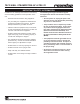
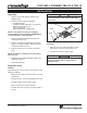
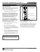
2. Remove the Top Cover, Generator Cover, and
Diffuser Plate (Figure 3).
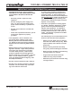
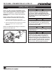
3. Insert the slanted end of the Calibration Tube into
Steam Generator hole and push in fully (Figure 4).
NOTE: If tube will not push in easily, the hole could
be clogged with mineral deposits. Use a flat-bladed
screwdriver to clear deposits out of the holes.
4. Put other end of Calibration Tubes into the
Calibration Cup (Figure 4).
5. Turn the power on.
6. Press the CYCLE START button and run two
complete cycles to purge all air from the tubes.
NOTES: Water may come out of the Calibration
Tubes with force. Hold the tubes and cup firmly.
7. Empty all water from the cup, then reinsert the
tubes back into the cup.
8. Press the CYCLE START button to run one cycle.
The cup should contain 0.8 oz (25 ml or 25 cc)
water. If the cup contains more or less than this
amount, proceed to Step 9.
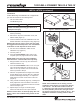
9. With the unit positioned at the edge of its location
surface (Edge of the counter, table, etc.) slide the
steamer forward approximately 3” to expose the
Water Volume Control on the button of the unit
(Figure 5).
10. Using a small screwdriver (Figure 5), carefully and
slowly adjust the control clockwise to increase or
counterclockwise to decrease the amount of water
volume used per cycle.
11. Repeat steps 7 through 10 until the proper
amount of water level in the cup is achieved.
NOTE: If steamer does not steam properly after cali-
bration, refer to the Troubleshooting section of this
manual.
CALIBRATION
your unit and consists of the following items:
CAUTION
This procedure exposes hot surfaces. Use
extreme care when performing procedure as to
INSTALLATION (continued)
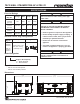
NOTE: If the Calibration Kit is missing, use the
Calibration Chart (Figure 11) to figure the approxi-
mate volume. Turn the water volume control to
the chart (left side), then look to the right to find
the volume closest to 0.8 oz. (25 ml or 25 cc). Turn
chart.
Figure 3. Steamer Components
Generator
Cover
Top Cover
"HOT"
CAUTION
"HOT"
CAUTION
STEAMING
CYCLE
START
READY
POWER
STEAMING
CYCLE
START
READY
POWER
Figure 4. Calibration Tube and Cup
Slanted End
CYCLE
STAR T
I
N
C
R
E
A
S
E
D
E
C
R
E
A
S
E
0
9
8
7
6
5
4
3
2
1
I
N
C
R
E
A
S
E
D
E
C
R
E
A
S
E
0
9
8
7
6
5
4
3
2
1