
Specifications
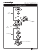

STS-200 STEAMER/SCALE
17
P/N 1010929 Rev. B 03/12
A.J. Antunes & Co.
Technical Theory of Operation
TEMPERATURE/STEAMING THEORY
When the Power Switch is on, line voltage flows to the
primary side of the step down transformer. The trans-
former’s secondary side supplies 12 VAC to terminals
T1 and T2 of the multifunctional temperature Control
Board.
Once powered, and provided that the generator surface
temperature is below 375ºF (190ºC), the multifunctional
temperature Control Board calls for heat by energizing
its on board mechanical relay. Once energized, the
mechanical relay closes its contacts, which allows line
voltage to flow to the generator.
thermistor monitors the internal generator temperature.
As the heat continues to increase, the thermistor’s
ohms begin to decrease. As the internal generator tem-
perature approaches 375-390º (190-198º C), the therm-
istor is generating approximately 790-665 ohms.
The multifunctional temperature Control Board receives
these ohms and then de-energizes the mechanical
relay since the heating circuit is satisfied. Then, the
mechanical relay contacts open, and the generator
stops heating.
The heating circuit cycles on and off as needed, even
at idle. Once the generator is up to temperature (a state
Air Bulb Switch is pressed and released to initiate a
steam cycle, air is directed rapidly through the pneu-
matic hose which then activates a pneumatic switch.
Once activated, the pneumatic switch contacts momen-
tarily close to complete a circuit to terminal J4 on the
multifunctional temperature Control Board.
-
tifunctional Control Board supplies line voltage to the
Solenoid Valve Coil for a split second. The Solenoid
Valve opens, and allows approximately 2-3 tablespoons
of water to be disbursed onto the Generator surface for
steaming. The water flashes into steam immediately
then rises up through the steam ports and steams the
product.
back on to indicate that the unit is ready to run another
steam cycle.
The multifunctional Control Board incorporates two status
call for heat and the Generator overheats, an automatic
resetting Hi-Limit Thermostat will trip and open the gen-
erator circuit and transformer circuit at approximately
450-470º F (232-243ºC).
NOTE: If this condition should repeat, the root
cause must be determined and corrected.
NOTE: The STS-200 Scale/Steamer is shipped with
a dual water pressure regulator assembly. The pri-
mary water pressure regulator is fixed at 30 PSI
and is not adjustable. The secondary water pres-
sure regulator is factory set and should remain
set between 7-9 PSI. It should only be momentarily
adjusted if required as per the maintenance section.
WEIGHT SCALE THEORY
As previously stated, when the power switch is on,
line voltage flows to the primary side of the step down
transformer. The transformer’s secondary side sup-
plies 12 VAC to the multifunctional temperature Control
Board terminals T1 and T2.
Once powered, terminal J1 on the multifunctional tem-
J1 of the scale Control Board by means of a wiring
harness. Once powered, the scale Control Board illumi-
nates its display. In addition, the two outer pins of the
scale Control Board’s J2 terminal powers up the load
cell’s “Green” and “Black” wires. The two center pins
receive a signal from the load cell’s “Red” and “White”
wires.
NOTE: The load cell is manufactured with an
integrated wiring harness. The loose end of this
harness plugs into the scale Control Board. The
removable top platform sits on 4 floating steel
pegs. The steel pegs are attached to a floating steel
cage (known as a Spider). The steel cage is attach-
es to the load cell. The Scale’s maximum operating
weight capacity is 4 lbs. The scale weighs in .1 oz
increments.
TECHNICAL THEORY OF OPERATION