
Owner`s manual


P/N 1010455 Rev. E 01/156
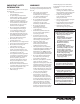
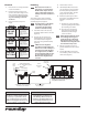
THIS UNIT IS DESIGNED TO
OPERATE ON 208 VOLTS
ONLY. APPLICATION WITH ANY
OTHER VOLTAGE SUPPLY
COMPLETELY VOIDS ALL
WARRANTY. PLEASE CHECK
YOUR LINE VOLTAGE BEFORE
INSERTING THIS PLUG INTO THE
RECEPTACLE.
WARNING WARNING
THIS UNIT IS DESIGNED TO
OPERATE ON 120 VOLTS
ONLY. APPLICATION WITH ANY
OTHER VOLTAGE SUPPLY
COMPLETELY VOIDS ALL
WARRANTY. PLEASE CHECK
YOUR LINE VOLTAGE BEFORE
INSERTING THIS PLUG INTO THE
RECEPTACLE.
WARNING WARNING
120 VAC
ONLY
208 VAC
ONLY
THIS APPLIANCE MUST BE
EARTHED (GROUNDED)
THIS APPLIANCE MUST BE
EARTHED (GROUNDED)
THIS APPLIANCE MUST BE
EARTHED (GROUNDED)
THIS APPLIANCE MUST BE
EARTHED (GROUNDED)
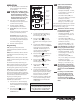
THIS UNIT IS DESIGNED TO
OPERATE ON 220-240 VOLTS
ONLY. APPLICATION WITH ANY
OTHER VOLTAGE SUPPLY
COMPLETELY VOIDS ALL
WARRANTY. PLEASE CHECK
YOUR LINE VOLTAGE BEFORE
INSERTING THIS PLUG INTO THE
RECEPTACLE.
WARNING WARNING
220-240
VAC ONLY
THIS APPLIANCE MUST BE
EARTHED (GROUNDED)
THIS APPLIANCE MUST BE
EARTHED (GROUNDED)
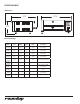
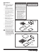
Electrical
1. Place the unit on a sturdy, level table
or other work surface.
2. Ensure that the line voltage corre-
sponds to the stated voltage on the
units specication label and power
cord warning tag. If you are unsure
of your Line Voltage, contact an
electrician.
3. Connect the unit to the power
supply.
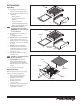
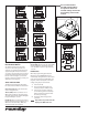
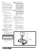
Figure 4. Connecting Water Supply
Plumbing
NOTE: Miracle Steamer models are
designed to use cold tap water.
Distilled water may be used to
reduce calcium/mineral deposit
buildup and reduce maintenance
costs.
These units require a direct cold water
hookup. A Water Inlet Hose and Strainer
Assembly (Figure 4) is supplied.
NOTE: Incoming water is controlled by
a normally closed (NC) sole-
noid valve located inside the
Steamer’s electrical housing.
1. Turn o the water valve (not sup-
plied) that supplies water to the unit
(Figure 4).
2. Connect the 1/4” (6.5 mm) I.D.
Flexible Tubing to the outlet side
of the Water Pressure Regulator
and secure using the Worm Clamp
(Figure 4).
NOTE: A Water Pressure Regulator
must rst be installed (Figure 4).
Failure to do so will result in poor
steaming and possible ooding.
For a single steamer, use Water
Pressure Regulator P/N 7000314.
For two adjacent steamers, use
Water Pressure Regulator P/N
7000235.
CAUTION
Water pressure must not exceed 30 psi
(2.1 kg/cm
2
or 207 kPa). Higher pressure
may cause poor performance or ood-
ing. To reduce water pressure, install a
Water Pressure Regulator, and set to 20–25
psi (1.4–1.7 kg/cm
2
or 138–172 kPa).
3. Turn the water valve on.
4. Hold the Quick Disconnect Insert
over a bucket, then press and hold
the white plastic tip until there’s a
good, steady water ow. This will
purge all air out of the line.
5. Release the plastic tip and check
the pressure on the Water Pressure
Regulator. It should read
20 psi.
a. If it reads less, increase the water
pressure by pulling the black knob
up and turning it clockwise.
b. If it reads more, decrease the
water pressure by pulling the
black knob up and turning it
counter clockwise.
NOTE: When adjusting the knob, relieve
the existing pressure by press-
ing the plastic tip on the Quick
Disconnect Insert for 3 seconds.
The Water Pressure Regulator will
then show the new pressure.
6. Once the regulator reads 20 psi,
push the black knob down to lock it
in place.
7. Push the Quick Disconnect Insert
into the tting at the rear of the unit
until it clicks (Figure 4).
Connect Quick
Disconnect
Insert Here
Inlet Hose & Strainer
Assy. (Supplied)
Optional Water Pressure Regulator
with Strainer (P/N 7000314)
Shut Off Valve
(Not Supplied)
Cold
Water
Flow
Flexible Nylon Braided
1/4 " I.D. Tubing (Not Supplied)
Quick
Disconnect
Insert
Worm
Clamp
NOTE: The use of only one strainer is
acceptable instead of two.
CAUTION
This equipment is to be installed to
comply with the basic plumbing code
of the Building Ocials and Code Ad-
ministrators, Inc. (BOCA) and the Food
Service Sanitation Manual of the Food
and Drug Administration (FDA).