RE AD Y Miracle Steamer Model MS-250/255 owner’s manual Manufacturing Numbers: 9100430, 9100435, 9100436, 9100437, 9100438, 9100440, 9100460, 9100462, 9100466, & 9100468 www.ajantunes.com P/N 1010455 Rev.
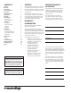
CONTENTS General Warranty Information Service/Technical Assistance Important Safety Information Warnings Specifications Dimensions Electrical Ratings Installation Unpacking Equipment Setup Electrical Plumbing Operation Programming Hi-Limit Reset Button Status Indicator LEDs Fault Codes Maintenance Daily Monthly Troubleshooting Replacement Parts Wiring Diagram Notes GENERAL 2 2 2 3 3 4 4 4 5 5 5 6 6 7 7 8 8 8 9 9 10 12 14 18 19 IMPORTANT This manual provides the safety, installation, and operating procedu
IMPORTANT SAFETY INFORMATION Use the following guidelines for safe operation of the unit. yy Read all instructions before using equipment. yy For your safety, the equipment is furnished with a properly grounded cord connector. Do not attempt to defeat the grounded connector. yy Install or locate the equipment only for its intended use as described in this manual. Do not use corrosive chemicals in this equipment.
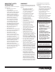
SPECIFICATIONS Dimensions 17-1/8” (435 MM) 20-3/4” (527 MM) 9-1/2” (234 MM) Electrical Ratings Model & Mfg. No. Volts Watts Amps Hertz Plug Description MS-250 9100430 208 3300 15.9 50/60 6-20P, 20 Amp., 250 VAC, Non Locking MS-250 9100435 208 3300 15.9 50/60 6-20P, 20 Amp., 250 VAC, Non Locking MS-250 9100436 230 3300 14.4 50/60 6-20P, 20 Amp., 250 VAC, Non Locking MS-250 9100437 230 3300 14.4 50/60 6-20P, 20 Amp., 250 VAC, Non Locking MS-250 9100438 230 3300 14.
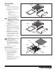
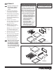
INSTALLATION Drip Pan Wire Trivet Unpacking 1. Remove the unit and all packing materials from the shipping carton. 2. The unit should come with the items listed below: • • • • • Owner’s Manual Authorized Service Agency Directory Inlet Hose Assembly Spatula Assembly (MS-250 only) Drawer Assembly (MS-255 only) Spatula Spatula Liner Figure 1. Washing Parts–MS-250 Only NOTE: If any parts are missing or damaged, contact A.J. Antunes IMMEDIATELY at 1-800-253-2991 or 1-630-784-1000. 3.
Electrical 1. Place the unit on a sturdy, level table or other work surface. 2. Ensure that the line voltage corresponds to the stated voltage on the units specification label and power cord warning tag. If you are unsure of your Line Voltage, contact an electrician. 3. Connect the unit to the power supply. WARNING THIS APPLIANCE MUST BE EARTHED (GROUNDED) WARNING THIS APPLIANCE MUST BE EARTHED (GROUNDED) THIS UNIT IS DESIGNED TO OPERATE ON 120 VOLTS ONLY.
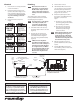
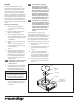
OPERATION 1. READY LIGHT 1. Turn the power on and allow the unit to preheat for approximately 20–30 minutes. READY MESSAGE DISPLAY NOTE: Do NOT push any button during warmup time. The flashing green Ready Light indicates that the unit is not warmed up. The green Ready Light will become steady when the unit is warmed up. 2. DOWN PRGM Push the Spatula or Drawer Assembly fully into the steamer. 4.
READY READY 15 1500 SINGLE SHOT SINGLE SHOT UP DOWN PRGM UP START/STOP DOWN PRGM NOTE: It is recommended that the SHO and H2O settings be adjusted to the recommended settings shown in the Programming section of this manual. START/STOP POWER CORD B. Total Cycle Minutes A. Total Cycle Time CAP HI-LIMIT RESET BUTTON READY READY 00 SHO SINGLE SHOT SINGLE SHOT UP DOWN PRGM START/STOP UP C. Total Cycle Seconds DOWN PRGM START/STOP D.
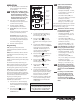
MAINTENANCE Daily NOTE: Frequency of cleaning is determined by water conditions, usage, and water filtration systems. 1. Turn the power off, unplug the power cord, and allow the unit to cool down before proceeding. 2. Check the Water Pressure Regulator gauge and verify that it reads 20–25 psi (1.4–1.7 kg/cm2 or 138–172 kPa). If not, adjust the pressure as described in the Installation section of this manual. 3. Check the rear water Quick Disconnect Fitting and Hose Clamp for leakage.
Monthly The Miracle Steamer utilizes an open steam Generator. Water sprayed onto the Generator surface flashes into steam immediately, but the minerals in the water do not steam, they stay on the Generator surface. A small amount of calcium/mineral deposits are needed for proper operation, but a buildup of excessive calcium/mineral deposits causes poor steaming efficiency and excessive moisture (wet steam), which will eventually severely hinder the steaming action. Cleaning Steam Generator 1.
O-RING TUBING STRAINER CUP Figure 12. Inlet Hose Assembly Checking and Cleaning the Water Strainer The Water Strainer protects your equipment from any foreign debris in the water line that could get into the food or damage the unit’s solenoid and cause the unit to leak or flood. It also protects the equipment’s proper and consistent operation from interference. To ensure proper and consistent steaming results, check the Water Pressure Regulator and Strainer Cup regularly.
TROUBLESHOOTING WARNING To avoid possible personal injury and/or damage to the unit, inspection, test and repair of electrical equipment should be performed by qualified service personnel. The unit should be unplugged when servicing. Problem Control Display is blank (power is on but indicator light is off ). Control Display is blank (power is on and indicator light is on). Possible Cause Plug the power cord into the appropriate outlet. The power cord and/or electrical plug is damaged.
Problem Unit heats but there is little or no steam produced Possible Cause Corrective Action Water Line Valve is closed. Check that the Water Line Valve is open. Filter Strainer is restricted. Check and clean the Filter Strainer as described in the Maintenance section of this manual. Quick Disconnect is not fully engaged at rear of the unit or is damaged. Remove and reengage the Quick Disconnect firmly until a click is heard. Replace if damaged. Low or no water pressure in the water line.
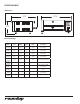
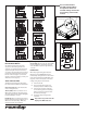
REPLACEMENT PARTS 95 95 74 74 64 17 99 15 57 20 21 90 36 11 36 90 54 54 10 54 41 7a 18 42 6 24 98 22 7 8 RE 13 AD Y 62 66 12 70 94 35 89 65 86 87 80 82 83 85 79 81 93 88 81 84 85 14 P/N 1010455 Rev.
RE AD Y RE AD Y 27 26 1 22 55 97 46 5 55 30 29 28 46 33 34 32 23 49 67 68 48 37 55 72 51 71 50 25 59 60 RE AD Y 69 55 19 57 P/N 1010455 Rev.
Item Part No. 1 0011123 2 7000652 3 0010584 5 4040145 6 7000237 7 0011314 7a 0013041 8 0021131 10 7000246 7000245 7000300 11 0300129 12 040P138* 13 040K251 14 05P2199* 15 0503431 17 0503433 18 0503434 19 0503435 21 0021314 21a 0504081 22 0503441 23 0503472 24 0700452 0700453 0700463 26 100P967 27 1001036 28 2000203 29 2000207 30 2040103 32 2040145 33 2040146 34 7000694 35 210K108 36 2100119 37 4050180 41 2100249 42 2100273 46 7000449 Description Solenoid Valve Assy. (Incl.
Dual Water Pressure Regulator Kit - Part No. 7000235 TO STEAMER Item Part No. 1 1 7000139 2 2030126 3 2030125 4 2040150 5 0503615 6 2190129 7 7000333 8 2080118 9 2190113 10 211P104 11 2040151 12 7000306 13 2170113 TO STEAMER 10 2 9 3 4 18 ! WARNING R91G-24K-NLN TEMP 125 F°MAX INLET 150 PSIG MAX OUTLET 125 PSIGMAX MADE IN USA IMI 5 MISUSE OF PRODUCTMAY CAUSE PERSONALINJURY.READ ASME INSTALATION/OPERATING INTRUCT 11 12 Description Qty. Elbow, Quick Disconnect - 1/4” Tubing 1/4” I.D.
WIRING DIAGRAM *NOTE: For 208-240 VAC units, the two primary coils are wired in series with one another. For 120 VAC units, the two primary coils are wired in parallel with one another. 18 P/N 1010455 Rev.
NOTES P/N 1010455 Rev.
LIMITED WARRANTY Equipment manufactured by Roundup Food Equipment Division of A.J. Antunes & Co. has been constructed of the finest materials available and manufactured to high quality standards. These units are warranted to be free from electrical and mechanical defects for a period of one (1) year from date of purchase under normal use and service, and when installed in accordance with manufacturer’s recommendations.