
Specifications

MS TECHNICAL MANUAL
LAST UPDATE 12-10-04
1060003 12/04
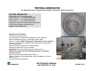
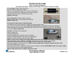
TESTING GENERATOR
See Generator under “Component Description & Function” before proceeding.
TESTING GENERATOR
Disconnect wires to isolate generator.
Verify 13 ohms +/- 1 for 208 volt generator
Verify 16 ohms +/- 1 for 230 volt generator
Verify 8 ohms +/- 1 for 120 volt generator
Check from each terminal to ground using at least
a 20M scale. Reading should be infinity.
Replace if fails either test.
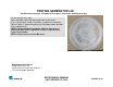
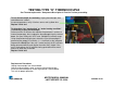
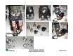
Replacement Procedures
Disconnect generator wiring.
Loosen brackets & remove thermocouple & hi-limit cap tube.
Remove compression nuts & steel tubes from the brass
elbow & “T” fitting. NOTE: Flexing the Teflon tubes may be required.
Unscrew (CCW) the brass elbow & fitting along with the teflon tubes
from the generator.
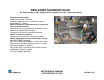
Remove generator wing nut, lid, & diffuser plate.
Remove the generator’s top 3 setscrews.
Cautiously, push the generator up & out of the chassis.
NOTE: Extra effort may be needed as generator is siliconed
onto the chassis.
Remove remaining dried silicone from chassis.
Apply 1/8” bead of red hi-temperature silicone (Supplied in kit) onto
the chassis &
the underside of the generator