
Specifications

MS TECHNICAL MANUAL
LAST UPDATE 12-10-04
1060003 12/04
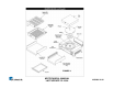
MS Component Description & Function
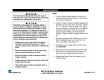
Power Switch: Double Pole Single Throw, turns the supply voltage On or Off to the unit’s internal line voltage
components. NOTE: The built in led illuminates when line voltage is present into & out of the switch. If not lit,
line voltage is not present into or out of the switch.
Squared Momentary Switch: Single Pole Single Throw, when pressed & released, it completes a low voltage
circuit to the control board. The control board then initiates a timed steam cycle.
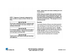
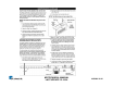
Step down Transformer: Consisting of 2 primary coils & 1 secondary coil, it steps down the incoming supply
voltage to operate the low voltage components (control board, solenoid valve, SS relay input side, momentary switch).
NOTE: If supply voltage is 208-240, the Primary coils are wired in series. If supply voltage is 120 volts, they are
wired in parallel.
NOTE: The secondary coil has a center tap (Terminal 8) that supplies 12 VAC. The two outer taps, (Terminals 6
& 10) supply 24 VAC. NOTE: The 12 VAC operates the control board. The 24 VAC operates the solenoid valve
used in (MS-250/255) or the water pump used in (MS-150/155).
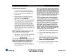
Control Board: Operates & controls all the timing, steaming, signaling, diagnostic, & heating functions. NOTE:
This control board incorporates 4 Led’s for status & diagnostic purposes. See “Led Display” in
Troubleshooting Section.
SS Relay: A Solid State, Single Pole Single Throw relay that is located at the rear of the unit & mounted on a heat
sink. When its input coil, (Terminals 3 + & 4 - ) is supplied 10-15 VDC by the control board, it allows the line voltage
contacts (Terminals 1 & 2) to close. Once they close, line voltage is supplied to the generator. NOTE: SS relays should
not be tested/diagnosed with an ohmmeter since this test is not reliable. Testing/Diagnosing an SS relay should
be conducted with the steamer & relay powered, and the use of a voltmeter. If faulty, this relay will permanently
fail open (No heat condition) or closed (Overheating condition). They do not fail intermittently. NOTE: Terminals
3 (+) & 4 (-) are polarity sensitive. The wiring can be inadvertently switched at the control board or at the relay if
either component is ever replaced. If so, 10-15 VDC will still be present at the relay, but it will not energize.
Therefore, the generator will not heat up. Always verify per wiring diagram.