
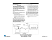
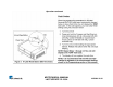
Specifications

MS TECHNICAL MANUAL
LAST UPDATE 12-10-04
1060003 12/04
MS
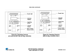
TECHNICAL THEORY OF OPERATION
When the power switch is on, line voltage flows to the primary side of the step down transformer. The transformer’s
secondary side supplies 12 & 24 VAC to the control board. Once powered, & provided that the generator temperature
is below 380 F (193 C), the control board calls for heat by supplying 10-15 VDC to the solid state relay terminals 3 (+) 4
(-). Once powered, the relay closes terminals 1 & 2, which allows line voltage to flow to the generator. As the generator
begins to heat up, a type “K” thermocouple monitors the internal generator temperature. As the heat continues to
increase, so does the thermocouple’s DC millivolts. Once the generator’s temperature rises to 380-420 F (193-215 C),
the thermocouple is generating approximately 7.5-9.0 DC millivolts. The control board receives these millivolts &
proceeds to remove the 10-15 VDC to the solid state relay since the heating circuit has now become satisfied. Then,
relay terminals 1 & 2 open up, and the generator stops heating. The heating circuit will cycle on & off as needed, even at
idle. When the squared momentary button or the “Single Shot”/”Start/Stop” touch pad button is pushed, it signals the
control board to supply 24 VAC to the solenoid valve used in the MS-250’s/255’s or the water pump used in MS-
150’s/155’s/355’s for approximately one second. The solenoid valve opens, or the water pump runs, and allows a shot of
water (Approximately ¾-1 oz 25-30 ml) to flow onto the generator surface for steaming.
NOTE: If the display is in a “Timed Cycle” (Counting Down), the control board will continue to activate the
solenoid valve or water pump for repeated shots of water, once every 20 seconds, and for the duration of the
cycle time displayed. See Programming. Since the generator’s circular cover is secured in place with a wing
nut, the steam is forced downward through the generator steam ports and onto the product. The Control
Board’s parameters can be custom programmed for the overall cycle steam time (CYC), as well as the interval
time in seconds (SHO) when each shot of water occurs, and also the water volume (H2O) used per each shot of
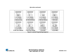
water (See Programming). This control board incorporates several Led’s for status & diagnostic purposes. See
“Led Layout” in troubleshooting section of the technical manual. An audio signal will sound for 3 seconds at
the end of a Timed Cycle. If the heating circuit continues to call for heat and the generator overheats, a manual
resettable Hi-Limit Thermostat will trip and open the generator circuit.
NOTE: If this condition should repeat, the root cause must be determined & corrected.