80 Kehoe Blvd. Carol Stream, Illinois 60188 USA 1-877-392-7854 (Tech Service).
MS STEAMER TRAINING MS TECHNICAL MANUAL LAST UPDATE 12-10-04 1060003 12/04
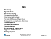
MS •Warranty •Specifications •Steamer warnings •Steamer installation •Operating instructions •Technical Theory of Operation •Component description & functions •Tools Required •Steamer Maintenance •Troubleshooting •Parts testing & replacement •Type “k” Millivolt chart •Wiring diagram MS TECHNICAL MANUAL LAST UPDATE 12-10-04 1060003 12/04
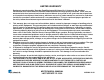
LIMITED WARRANTY Equipment manufactured by Roundup Food Equipment Division of A.J. Antunes & Co. has been constructed of the finest materials available and manufactured to high quality standards. These units are warranted to be free from mechanical and electrical defects for a period of one year from date of purchase or 18 months from shipment from factory, whichever occurs first, under normal use and service, and when installed in accordance with manufacturer’s recommendations.
MS TECHNICAL MANUAL LAST UPDATE 12-10-04 1060003 12/04
MS TECHNICAL MANUAL LAST UPDATE 12-10-04 1060003 12/04
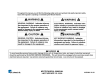
In addition to the warnings and cautions in this manual, use the following guidelines for safe operation of the unit. • Read all instructions before using equipment. • For your safety, the equipment is furnished with a properly grounded cord connector. Do not attempt to defeat the grounded connector. • Install or locate the equipment only for its intend- ed use as described in this manual. Do not use corrosive chemicals in this equipment.
• Check with a qualified electrician if you are in doubt as to whether the appliance is properly grounded. • This equipment is to be installed to comply with the basic plumbing code of the Building Officials and Code Administrators, Inc. (BOCA) and the Food Service Sanitation Manual of the Food and Drug Administration (FDA). • If the supply cord is damaged, it must be replaced by the manufacturer or its service agent, or a similarly qualified person. • Do not clean this appliance with a water jet.
MS TECHNICAL MANUAL LAST UPDATE 12-10-04 1060003 12/04
MS TECHNICAL MANUAL LAST UPDATE 12-10-04 1060003 12/04
MS TECHNICAL MANUAL LAST UPDATE 12-10-04 1060003 12/04
MS TECHNICAL MANUAL LAST UPDATE 12-10-04 1060003 12/04
Operation continued MS TECHNICAL MANUAL LAST UPDATE 12-10-04 1060003 12/04
MS TECHNICAL MANUAL LAST UPDATE 12-10-04 1060003 12/04
Operation continued MS TECHNICAL MANUAL LAST UPDATE 12-10-04 1060003 12/04
MS TECHNICAL MANUAL LAST UPDATE 12-10-04 1060003 12/04
Operation continued MS TECHNICAL MANUAL LAST UPDATE 12-10-04 1060003 12/04
MS TECHNICAL MANUAL LAST UPDATE 12-10-04 1060003 12/04
Operation continued MS TECHNICAL MANUAL LAST UPDATE 12-10-04 1060003 12/04
MS TECHNICAL THEORY OF OPERATION When the power switch is on, line voltage flows to the primary side of the step down transformer. The transformer’s secondary side supplies 12 & 24 VAC to the control board. Once powered, & provided that the generator temperature is below 380 F (193 C), the control board calls for heat by supplying 10-15 VDC to the solid state relay terminals 3 (+) 4 (-). Once powered, the relay closes terminals 1 & 2, which allows line voltage to flow to the generator.
MS Component Description & Function Power Switch: Double Pole Single Throw, turns the supply voltage On or Off to the unit’s internal line voltage components. NOTE: The built in led illuminates when line voltage is present into & out of the switch. If not lit, line voltage is not present into or out of the switch. Squared Momentary Switch: Single Pole Single Throw, when pressed & released, it completes a low voltage circuit to the control board. The control board then initiates a timed steam cycle.
MS Component Description & Function Generator: Also known as a heating plate, it is a circular shaped aluminum casting consisting of a permanently integrated heating element. When powered, it generates heat to convert a shot of water (approximately ¾-1oz 25-30 ml) into steam instantaneously. NOTE: Theses generators come in 120, 208, & 230 volt versions & are voltage specific. They must operate on the proper voltage supply, otherwise, they are prone to premature failure.
MS Component Description & Function Solenoid Valve: Used in direct water feed units the MS-250/255, it is a normally closed 24 VAC water valve that is electrically operated for approximately one second by the control board during a steam cycle. NOTE: The “IN” & “OUT” markings on the valve body must correspond with water flow, otherwise, the valve will leak through. If the valve is installed correctly and leaking through, debris/speck has become lodged within the plunger & body area.
MS Component Description & Function Audio Signal: An audio device located at the bottom of the control board. At the completion of steam cycle, the control board supplies approximately 10-15 VDC to it for 3 seconds. NOTE: The signal can be replaced separately if it fails. It can be tested with a 9 VDC battery. Green “Ready” light: It is located at the front of the unit and attached to the control board.
TOOLS REQUIRED FOR PROPER TROUBLESHOOTING (VOM) Volt Ohm Meter (digital or analog) DC millivolt meter (unless integrated into VOM) Clamp type amp meter (digital or analog) Flat blade screwdriver ¼ ", 3/16" Open end wrench ½" Adjustable wrench 6" ¼“ ratchet and socket Channel locks Wire cutter, crimper, stripper Wire brush Needle nose pliers.
MS TECHNICAL MANUAL LAST UPDATE 12-10-04 1060003 12/04
MS TECHNICAL MANUAL LAST UPDATE 12-10-04 1060003 12/04
MS TECHNICAL MANUAL LAST UPDATE 12-10-04 1060003 12/04
FIGURE 8 MS TECHNICAL MANUAL LAST UPDATE 12-10-04 1060003 12/04
MS TECHNICAL MANUAL LAST UPDATE 12-10-04 1060003 12/04
TROUBLE SHOOTING Problem Control Display is Blank (power On/Off switch is On but indicator light is off). Control Display is blank (power On/Off switch is on and indicator light is on). Possible Cause The power cord is not correctly plugged in. Plug the power cord into the appropriate outlet. The power cord and/or electrical plug is damaged. Inspect electrical wire, plug, and receptacle. The main electrical panel circuit breaker is off or has been tripped. Reset circuit breaker.
TROUBLE SHOOTING Problem Water leaking inside electrical hous-ing. “ERR” appears in the Control Display. Possible Cause Corrective Action Pinhole leak in rubber hoses (MS-150/155/355). Replace hoses. Loose or damaged water line tubes and/or fittings inside electrical hous-ing. Apply teflon tape, Tighten or replace tubes and/or fit-tings. Programming and/or SHO and H2O values were adjusted/changed improperly. Reset the Control Board as described in the Programing section of this manual.
TROUBLE SHOOTING Problem Unit heats but there is little or no steam produced and/or The product requires more steaming than usual. Possible Cause Corrective Action Water Line Valve is closed (MS-250/255). Check that the Water Line Valve is Open Filter Strainer is restricted. Check and clean the Filter Strainer. Quick disconnect is not fully engaged at rear of the unit or is damaged (MS-250/255). Remove and reengage the Quick Disconnect firmly until a “click” is heard. Replace if damaged.
TROUBLE SHOOTING Problem Possible cause Corrective action MS TECHNICAL MANUAL LAST UPDATE 12-10-04 1060003 12/04
Parts Testing & Replacement Procedures MS TECHNICAL MANUAL LAST UPDATE 12-10-04 1060003 12/04
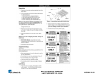
Testing Power Switch See Power Switch under “Component Description & Function” before proceeding. TESTING POWER SWITCH Disconnect wires to isolate switch. Turn switch to the “On” position. Verify continuity across terminals 1 & 2, then 4 & 5. Next, turn switch to the “Off” position. Reading should now be infinity. Replace if fails test. 4 5 1 2 Replacement Procedures Disconnect power switch wires (Mark for reinstallation). Squeeze locking tabs inward & push switch out towards front of unit.
TESTING SQUARED MOMENTARY SWITCH See Momentary Switch under “Component Description & Function” before proceeding. TESTING SQUARED MOMENTARY SWITCH Disconnect wires to isolate switch. Press & hold switch in. Verify continuity across both terminals. Next, release switch. Reading should now be infinity. Replace if fails test. Replacement Procedures Disconnect switch wires. Squeeze locking tabs inward & push switch out towards front of unit. Snap new switch into place until flush.
TESTING STEPDOWN TRANSFORMER See Transformer under “Component Description & Function” before proceeding TESTING STEP DOWN TRANSFORMER Disconnect wires to isolate transformer coils. Terminals 1 & 2 (15-19 ohms) Terminals 4 & 5 (17-23 ohms) Terminals 6 & 10 (0.6 ohms) Terminals 6 & 8 (0.3 ohms) Terminals 8 & 10 (0.3 ohms) All readings +/- 10% Replace if any coil fails test. 6 8 10 1 2 4 5 Replacement Procedures Disconnect transformer wires (Mark for reinstallation).
TESTING CONTROL BOARD See Control Board under “Component Description & Function” before proceeding. TESTING CONTROL BOARD Control Board must be tested while powered up (See Technical Theory of Operation). Check for proper VAC/VDC input & output. Replace if it fails any of its functions. Replacement Procedures Disconnect control board wiring & unplug thermocouple (Mark for reinstallation). Remove the nuts & the control board. Install new control board & secure with the nuts.
TESTING SS RELAY See SS Relay under “Component Description & Function” before proceeding. TESTING SS RELAY To determine if relay contacts are stuck closed (Unit overheating): Disconnect RED wire from relay terminal 3 (+). Clamp an amp meter onto the black wire at relay terminal 1 or 2. Is there any amp draw? If yes, replace relay. To determine if relay contacts are stuck open (Unit not heating): Ensure the control board & relay are wired per the wiring diagram.
TESTING GENERATOR See Generator under “Component Description & Function” before proceeding. TESTING GENERATOR Disconnect wires to isolate generator. Verify 13 ohms +/- 1 for 208 volt generator Verify 16 ohms +/- 1 for 230 volt generator Verify 8 ohms +/- 1 for 120 volt generator Check from each terminal to ground using at least a 20M scale. Reading should be infinity. Replace if fails either test. Replacement Procedures Disconnect generator wiring.
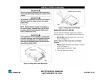
GENERATOR CONTINUED NOTE: Failure to apply silicone will allow steam to enter the electrical compartment. Seat new generator in place & secure with new setscrews. NOTE: Replacement generator will have artificial lime deposits on it that are required for proper steaming characteristics. Remove excess silicone & smooth to a neat finish. Apply Teflon tape to the threads of the Teflon tubes & screw into generator until snug. Reinstall the steel tubes, compression nuts, & secure.
TESTING GENERATOR LID See Generator Lid under “Component Description & Function” before proceeding. Ensure the wing nut is tight. Does noticeable steam leak out the perimeter of the cover? If yes, remove cover, check it for flatness, & observe its underside. Does the outer ½” perimeter contain any noticeable calcium buildup? If yes, replace cover. NOTE: Calcium buildup at perimeter indicates that steam is leaking out from there. If perimeter is shiny, it indicates that steam is not leaking.
TESTING TYPE ”K” THERMOCOUPLE See Thermocouple under “Component Description & Function” before proceeding To test thermocouple for continuity: Unplug thermocouple from control board to isolate it. At room temperature, verify 2-3 ohms across red & yellow wire. Replace if fails test. To determine if an “overheating” or “under heating condition” is caused by a faulty thermocouple: Preheat unit for 15 minutes then monitor the generator’s surface, or internal temperature.
TESTING HI-LIMIT See Hi-limit under “Component Description & Function” before proceeding. To test for continuity: Disconnect wires to isolate hi-limit. Verify continuity across the terminals. Replace if fails test. To determine if hi-limit is tripping prematurely: Monitor the generator’s surface or internal temperature. Does hi-limit trip below 450 F (232 C)? If yes, replace hi-limit.
TESTING SOLENOID VALVE (Direct water feed units only) See Solenoid Valve under “Component Description & Function” before proceeding. To test the solenoid valve coil: Disconnect wires to isolate solenoid valve coil. Verify 8-20 ohms. Replace if fails test. To determine if solenoid valve is leaking through: Turn power off & disconnect water line from rear. Dry up any water that is present on the generator surface. Once dry, reconnect the water line ONLY.
MS TECHNICAL MANUAL LAST UPDATE 12-10-04 1060003 12/04
REPLACING SOLENOID VALVE See Solenoid Valve under “Component Description & Function” before proceeding. Replacement Procedures Disconnect solenoid valve wires. Remove compression nuts & steel tubes from the brass elbow & “T” fitting. NOTE: Flexing the Teflon tubes may be required to ease nut & tube removal. Remove the two rear female quick disconnect screws. Remove the solenoid/QD assembly. Unscrew the QD from the solenoid valve body. NOTE: Vise may be required.
TESTING WATER PUMP (Water Tank Equipped Models) See Water Pump under “Component Description & Function” before proceeding To Test Diode: Remove diode from pump. Set your VOM to “Diode” check setting. Measure across both diode terminals & note the reading. Next, reverse your VOM leads on diode & measure again. Reading should be infinity one way & 470-520 the other way. Replace if fails test. To Test Pump Coil: Remove diode from pump. Verify 4-6 ohms across the 2 orange wires on pump. Replace if fails test.
REPLACING WATER PUMP Water Tank Equipped Models See Water Pump under “Component Description & Function” before proceeding Replacement procedures Turn power off & unplug unit. Drain the water tank. Disconnect pump wires. Remove rubber hoses, bottom mounting nuts, & pump. Install new pump assembly & secure with the nuts. NOTE: Arrow on pump body should correspond with water flow Reinstall rubber hoses & wiring. Verify the water tank filter is properly installed & not torn. Replace if needed.
TESTING QUICK DISCONNECT (FEMALE) Direct Water Feed Units Only See Quick Disconnect Female under “Component Description & Function” before proceeding The Female QD is generally trouble free. If the locking mechanism (Tab, spring, pin) are missing or damaged, the female QD must be replaced. Replacement Procedures Disconnect the solenoid valve wires. Remove compression nuts & steel tubes from the brass elbow & “T” fitting. NOTE: Flexing the Teflon tubes may be required to ease nut & tube removal.
TESTING QUICK DISCONNECT (MALE) Direct Water Feed Units Only See Quick Disconnect Male under “Component Description & Function” before proceeding. Verify the white nylon tip is not chipped, broken, or damaged. NOTE: The tip should protrude at least 1/8”. Verify it retracts when depressed, & protrudes when released. NOTE: If water does not flow when the tip is depressed, it generally indicates there is no water pressure in line.
TESTING AUDIO SIGNAL See Audio Signal under “Component Description & Function Does the audio sound for 3 seconds towards the end of a cycle? If no, did the yellow (Audio) Led turn on for 3 seconds? If yes, replace audio signal. Replacement Procedures Using a small screw driver, straighten the locking pin behind the audio signal. Pull & remove audio signal. Install new audio signal & bend locking pin down. Test unit for proper operation.
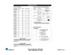
THERMOELECTRIC VOLTAGE IN MILLIVOLTS TYPE “K” THERMOCOUPLE READINGS + OR – 1 MILLIVOLT °F 300 310 320 330 340 350 360 370 380 390 MV 6.1 6.3 6.5 6.7 6.9 7.2 7.4 7.6 7.8 8.0 °F 400 410 420 430 440 450 460 470 480 490 MV 8.3 8.5 8.7 8.9 9.2 9.4 9.6 9.8 10.1 10.3 °F 500 510 520 530 540 550 560 570 580 590 600 MS TECHNICAL MANUAL LAST UPDATE 12-10-04 MV 10.5 10.7 11.0 11.2 11.4 11.7 11.9 12.1 12.3 12.6 12.
MS TECHNICAL MANUAL LAST UPDATE 12-10-04 1060003 12/04
MS TECHNICAL MANUAL LAST UPDATE 12-10-04 1060003 12/04