
Specifications


Project No.:ZKT-211130L6532E
Page 29 of 38
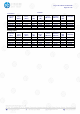
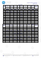
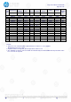
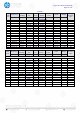
5. BANDWIDTH OF FREQUENCY BAND EDGE
5.1 TEST REQUIREMENT:
Test Requirement:
FCC Part15 C Section 15.209 and 15.205
Test Method:
ANSI C63.10: 2013
Test Frequency Range:
All of the restrict bands were tested, only the worst band’s (2310MHz
to 2500MHz) data was showed.
Test site:
Measurement Distance: 3m
Receiver setup:
Frequency
Detector
RBW
VBW
Value
Above
1GHz
Peak
1MHz
3MHz
Peak
Average
1MHz
3MHz
Average
Emissions radiated outside of the specified frequency bands, except for harmonics, shall be
attenuated by at least 50 dB below the level of the fundamental or to the general radiated emission limits in
§ 15.209, whichever is the lesser attenuation
5.2 TEST PROCEDURE
Above 1GHz test procedure as below:
a.
1. The EUT was placed on the top of a rotating table 1.5 meters above the ground at a 3 meter camber.
The table was rotated 360 degrees to determine the position of the highest radiation.
b.
The EUT was set 3 meters away from the interference-receiving antenna, which was mounted on the
top of a variable-height antenna tower.
c.
The antenna height is varied from one meter to four meters above the ground to determine the
maximum value of the field strength. Both horizontal and vertical polarizations of the antenna are set to
make the measurement.
d.
For each suspected emission, the EUT was arranged to its worst case and then the antenna was tuned
to heights from 1 meter to 4 meters and the rota table was turned from 0 degrees to 360 degrees to find
the maximum reading.
e.
The test-receiver system was set to Peak Detect Function and Specified Bandwidth with Maximum Hold
Mode.
f.
If the emission level of the EUT in peak mode was 10dB lower than the limit specified, then testing could
be stopped and the peak values of the EUT would be reported. Otherwise the emissions that did not
have 10dB margin would be re-tested one by one using peak, quasi-peak or average method as
specified and then reported in a data sheet.
g.
Test the EUT in the lowest channel, the Highest channel
Note:
Both horizontal and vertical antenna polarities were tested
and performed pretest to three orthogonal axis. The worst case emissions were reported
5.3 DEVIATION FROM TEST STANDARD
No deviation
5.4 TEST SETUP