
Specifications
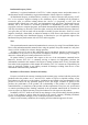
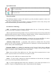


Table Of Contents

3. Device design and principle of operation
3.1. Purpose of sockets
Fig. 2. Device layout (1 — antenna, 2 – contact pads, 3 – magnet, 4 — mounting holes,
5 — LED indicator, 6 – housing, 7 – USB type C connector)
3.2. Purpose of indication
Indicator state Device state
Radio is disabled. Connection limit is 0.
Searching for a free radio channel or the radio channel is set to a specific value and this
channel is occupied by another device.
This device found a channel to work with and now waits for wireless sockets. Color is the
channel identification, different channels will have different colors.
This access point has at least one other client connected to it, the color will be identical on
both devices.
Device is in firmware update mode.
Device error, it will be restarted in a few seconds.
Hardware error, the number of red blinks is the error code.
7