
Owner`s manual
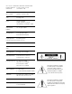

J - Detachable Power Cord Socket - Plug the Detachable
Power Cord into this socket (see Figure 1). The SFL-1 is factory
set for the correct operating voltage for the area in which it is
sold (see shipping box for voltage setting). If a different operat-
ing voltage is required, please contact an authorized Sonic
Frontiers dealer, distributor or the factory directly.
K - AC Line Fuse - This is the AC fuse socket. The fuse may be
accessed with a small flat-bladed screwdriver by turning the
fuse cap a 1/2 turn counterclockwise to unlock a spring that
ejects the fuse holder out. The unit is factory installed with
“fast-blo” .5 Amp 250V (0.25” x 1.25”) for 100-120V use
or .25 Amp 250V (0.25” x 1.25”) for 200-240V use.
L - Sets 1 & 2 of Left and Right RCA S i n g l e - E n d e d
Main Outputs - These outputs should be used when con-
necting to the single-ended RCA inputs on other units, such as
a power amplifier or crossover unit; connect left channel to left
channel and right channel to right channel. The two sets of out-
puts allow for easier biamping and greater flexibility over a sin-
gle set of output jacks when dealing with components such as
electronic crossovers, powered subwoofers, etc.
M
-Left and Right RCA Single-Ended Tape Output - This
output connects to the single-ended RCA input of a tape deck;
left channel to left channel and right channel to right channel.
These outputs are not operational when the Direct/Normal
Switch (B) is in the DIRECT mode, or when the Tape/Source
Switch (C) is in the TAPE mode.
N
-Left and Right RCA Single-Ended Tape Input - This
input accepts a single-ended RCA input connection from a
tape source; left channel to left channel and right channel to
right channel.
O
-Left and Right RCA Single-Ended Direct Input - This
input accepts a single-ended RCA input connection from a pre-
ferred line level source to achieve the highest possible sonic perfor-
mance, bypassing unnecessary control functions; left channel to left
channel and right channel to right channel. This input is selected by
placing the Direct/Normal Switch (B) in the DIRECT position.
P - Left and Right RCA Single-Ended Auxiliary 2 Input
- This input accepts a single-ended RCA input connection from
any line level signal source; left channel to left channel and
right channel to right channel. It is selected via the Source
Selector Switch (A).
Q
-Left and Right RCA Single-Ended Auxiliary 1 Input
- This input accepts a single-ended RCA input connection from
any line level signal source; left channel to left channel and
right channel to right channel. It is selected via the Source
Selector Switch (A).
R - Left and Right RCA Single-Ended Tuner Input - This
input accepts a single-ended RCA connection from a tuner
source; left channel to left channel and right channel to right
channel. It is selected via the Source Selector Switch (A).
S - Left and Right RCA Single-Ended CD Input - This
input accepts a single-ended RCA connection from a Compact
Disc Player or Digital-to-Analogue Converter; left channel to left
channel and right channel to right channel. It is selected via the
Source Selector Switch (A).
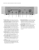
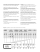
J K M N O P Q R SL
Figure 1 - Align socket pins to corresponding holes and push together firmly.
Back view of the Signature version with Kimber jacks.