
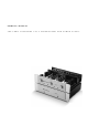
Owner`s manual
INSERTION OF THE TUBES
The SFL-2 comes with eight 6922 (6DJ8-type) tubes, individual-
ly boxed and bagged along with a cotton glove, allen key,
P e a r l
T M
Tube Coolers and screws for fastening the SFL-2 cover.
Please read and follow these instructions carefully. Great care
was taken in the testing, selection and matching of the supplied
tubes in order to ensure proper operation of the unit. Failure to
follow these instructions will cause the SFL-2 Preamplifier to
suffer in performance and sound quality.
1. Be sure that the AC Detachable Power Cord is disconnected
from the SFL-2 Power Supply b e f o r e removing the Preamplifier
chassis cover.
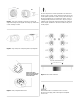
2. Using the allen key, remove the cover of the SFL-2
Preamplifier. For convenience, there will be only two screws
holding it in place.
3. When handling the tubes, it is recommended the cotton
gloves provided be worn to prevent skin oils from depositing
on the glass surface and possibly causing the tube to become
prematurely “gassy”, thereby shortening the tube’s useful oper-
ating life.
4. Inspect the tubes for code markings. They will be coded
individually, each with one of the following codes: LV1, LV2,
LV3, LV4, V1, V2, V3 and V4.
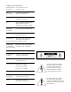
5. Inspect the tube sockets in the SFL-2 Preamplifier for the
codes matching the codes on the tubes. The coding is printed
on the PCB circuit board beside the tube sockets. See Figure 3
for further clarification.
6. Take the LV1 tube and inspect the pins noting the larger
space between two of the pins. This space will align with the
same larger space between two of the pin holes on the socket.
Insert the LV1 tube into the LV1 tube socket, making sure all
pins and pin holes are aligned (see Figure 4). Do not force the
tube into the socket. Rock the tube gently while pushing slowly
until the tube is firmly seated. Repeat this step for the remaining
tubes, LV2 tube to the LV2 tube socket, LV3 tube to the LV3
tube socket, LV4 tube to the LV4 tube socket, V1 tube to the V1
tube socket, V2 tube to the V2 tube socket, V3 tube to the V3
tube socket and V4 tube to the V4 tube socket.
7. Install the supplied Pearl
T M
Tube coolers over each tube,
keeping the bottom edge of the cooler away from the top sur-
face of the socket. Next, install the supplied rubber “O”-rings -
2 rings per cooler, evenly spaced at 1/3 from the bottom and
1/3 from the top to clamp the cooler firmly around the tube.
8. Replace the cover and fasten it with the screws provided.
The SFL-2 Preamplifier is now ready for operation.
REPLACEMENT OF THE TUBES
Sonic Frontiers strongly discourages non-factory replacement of
the tubes. The eight 6922 (6DJ8-type) tubes are measured,
selected, and matched in balanced pairs - channel to channel
and triode section to triode section - for optimum performance.
If replacement tubes are needed or desired, contact Sonic
Frontiers for assistance.
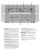
SFL-2 PREAMPLIFIER AND
POWER SUPPLY PLACEMENT
Under n o circumstance should the SFL-2 Power Supply be
placed directly on top of the SFL-2 Preamplifier. This will n o t
allow adequate ventilation, and overheating will result.
The units may be stacked if the Preamplifier is situated on top
of the Power Supply. A better arrangement would be to place
the units side by side or on separate shelves and free from
obstruction which may inhibit adequate ventilation.
Allow at least 6” (15 cm) of clear space above the
Preamplifier chassis for proper ventilation.
TROUBLE SHOOTING
If the SFL-2 Preamplifier is not producing sound, please check
each of the following:
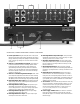
1. Check that the AC Detachable Power Cord is plugged into
the SFL-2 Power Supply’s Detachable Power Cord Socket (K)
and is connected to a l i v e source of AC power. For instance, if
using a power bar, check that the bar is turned on.
2. Be sure that the Operate/Standby Switch (U) on the Power
Supply chassis is in the “up” (operate) position.
3. Check that the proper input has been selected with the
Selector Switch (N) on the Preamplifier chassis.
4. Ensure that the Mute/Operate Switch (R) is in the “down”
(operate) position.
5. Check that b o t h AC Line Fuses (L) at the rear of the Power
Supply chassis are good. Be sure to f i r s t unplug the AC
Detachable Power Cord from the Power Supply.
6. Check to be sure that all eight 6922 tubes are correctly and
firmly seated in their tube sockets and that all nine contact pins
are inserted in each socket (i.e. no pins are bent over). Verify
that an orange glow is visible from inside of each tube when
the unit is on.
7. If you are still experiencing any difficulty with your SFL-2
Preamplifier, contact your dealer or distributor for assistance.