
Owner`s manual
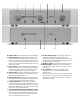
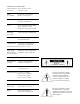

Top view of tube socket order
( Front (faceplate) of the SFL-2 )
Figure 3 - Tube and tube socket order.
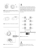
Figure 4 - Tube pin alignment with the socket.
Note the larger space
between two of the pins and
holes for proper alignment
of tube and socket.
W A R N I N G
DO NOT ADJUST the controls represented in the shaded box
shown in Figure 3 below. These controls have been factory set
for the optimum performance (both sonically and electrically) of
the SFL-2 Preamplifier. Do not adjust these controls - doing so
will d e g r a d e the performance of the SFL-2. They may o n l y b e
adjusted using specialized test equipment that only authorized
service depots, distributors or the Sonic Frontiers factory have
for this purpose.
Figure 2 - Align socket pins to corresponding holes and push together.
Figure 1 - Align pins in receptacle (A) to pin holes in connector (M),
align notches to ridges and push together. Turn locking ring clockwise until
it “clicks” indicating it is locked.
A
M
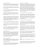
W A R N I N G
D I S C O N N E C T the AC Detachable Power Cord from
the SFL-2 Power Supply b e f o r e removing the Preamplifier
chassis cover.