
Specifications

4
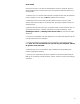
C Power Switch
D Standby Switch
E Power LED (Green - Power; Red - Mute)
F Standby LED (Green - Operate; Red - Standby)
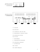
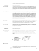
G Detachable Power Cord Socket
H Fuse Location
I Balanced XLR Input
J Single-Ended RCA Non-Inverting Input
K Single-Ended RCA Inverting Input
L Input Selector Switch
M Ground Post
N Loudspeaker Binding Posts
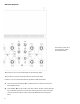
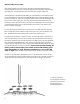
This drawing is referred to
as the “Front Panel” within
the instructional text.
This drawing is referred to
as the “Rear Panel” within
the instructional text.