
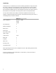
Specifications

3
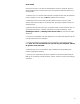
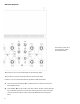
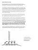
Reference Diagrams
This drawing is referred to
as the “Tube Top” within
the instructional text.
Tube locations V1 to V4 indicate placement for the four 6922 tubes.
Tube locations V5 and V6 indicate placement for the two 5687 tubes.
Locations V7 to V14 indicate placement for the 6550C/KT88 power tubes.
A Holes on the Tube Top labeled “A” are LED indicators for the bias of the power
tubes situated nearest.
B Holes labeled “B” are the location of the bias controls. The bias controls adjust the
bias of the tube which they are joined to by the lines. Direction arrows around the
controls indicate the rotation of the control to INCREASE the bias of the power
tubes.