
Installation guide

Last revision 12/00 4
SX-9
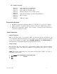
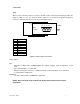
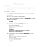
There are 5 connectors located on the SX-9 audio board's metal mounting bracket. See Figure 5.
Audio Output:
Line:
Balanced - Nine pin D connector 0 to +26dBu(digital clipping) - software selectable
with 1dBu resolution, with an impedance of 50 ohms and a load impedance of 600 ohms
Unbalanced - 1/8” stereo mini jack 2VRMS/+6dBV max (digital clipping), with an
impedance of 470 ohms and a load impedance of 10k ohms
Unbalanced - 1/8” stereo mini jack 2VRMS/+6dBV max (digital clipping), with
an impedance of 470 ohms and a load impedance of 10k ohms
Figure 5: SX-9 Connector Locations
AES/EBU Digital:
7 pin Mini DIN jack. Professional AES/EBU: EIAJ CP-340 Type I / IEC-958 Pro or
Consumer S/PDIF: EIAJ CP-340 Type II / IEC-958 Consumer
NOTE: We recommend using the balanced Analog I/O for professional broadcast
applications
Stereo Mini Headphones
DB-9 Balanced Out
Unbalanced Right
Unbalanced Left
SX-9
JP1
1
LEFT
RIGHT
GND
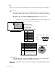
AES/EBU, S/PDIF Digital Out
Pin Assignment
1Gnd
2Nc
3Nc
4 Right Out -
5 Left Out -
6Nc
7Nc
8 Right Out +
9 Left Out +
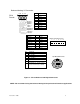
Pin Assignment
1 Ground
2Nc
3 Out - AES/EBU+ or S/PDIF+
4Nc
5 Out - AES/EBU - or S/PDIF-
6Nc
7 AES/SPDIF sense - This line should be
connected to Ground for AES/EBU
operation and left floating for S/PDIF
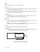
D
B-9
F
emale
Balanced Analog I /O Connector
12345
6789
1
3
5
2
4
6
7 pin Mini DIN Female
7