
Installation manual

Engineering - 65
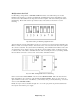
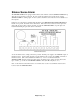
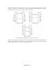
On the comm cable, some of the signals need to be shorted together within the D-sub connector. Others
need to be connected across the cable to pins at the other end. Below are wiring diagrams for each cable
configuration: 9-pin to 9-pin, 25-pin to 25-pin, and 9-pin to 25-pin.
Comm cable wiring configurations for 9-and 25-pin connectors.
Note: Due to the large voltage swings of RS-232, it is not advisable to run a comm cable through a patch
panel or multi-pair cable also containing audio. (The data stream may be heard on any of the audio lines
inside the patch panel.) Try to route it on a separate shielded wire.