
Installation manual

Engineering - 64
Communications Cable
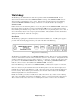
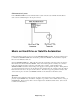
There are several instances during a SMARTCASTER installation in which a communications, (comm),
cable is needed. Connections with a Remote Record unit or CD Server unit to the SMARTCASTER all
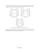
require a comm cable. The comm cable is linked between the serial, RS-232, ports of each computer.
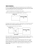
In the case that a comm cable needs to be built or repaired, two female D-Sub connectors are need. These
should be in the 9 pin or 25-pin configuration. A check of the serial ports to be linked must be made.
Some serial ports use the 25 pin connector, and others use the 9 pin connector. The cable should consist
of two conductors plus a shield.
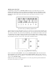
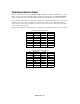
Each pin on the cable has a special function for serial RS-232 communication between the two computers:
9 Pin RS-232 Communications
Pin
Abbreviation
Name
1 DCD
Data Carrier Detect
2 RX
Receive Data
3 TX
Transmit Data
4 DTR
Data Terminal Ready
5 GND
Ground
6 DSR
Data Set Ready
7 RTS
Request To Send
8 CTS
Clear To Send
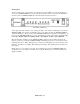
25 Pin RS-232 Communications
Pin
Abbreviation
Name
2 TX
Transmit Data
3 RX
Receive Data
4 RTS
Request To Send
5 CTS
Clear To Send
6 DSR
Data Set Ready
7 GND
Ground
8 DCD
Data Carrier Detect
20 DTR
Data Terminal Ready