
Installation manual

Engineering - 63
Opto-Isolation
Presently, most SMARTCASTERS are shipped in an Opto-Isolation mode. This modification helps
protect the unit against lightning damage and damage caused by electrical surges. It also allows the unit
to operate in high RF fields that might cause random Break firings if the control circuits are not isolated.
(Units using the 8x4 Switcher do not operate with Opto-Isolation.)
For the non-technical, here is a brief description of Opto-Isolation:
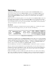
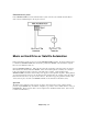
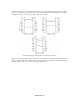
A standard, non-isolated circuit uses a direct, hard-wired connection from the outside world to the
sensitive computer chips located inside the SMARTCASTER. (See figure below.)
The integrated circuit chip, which is very sensitive to voltage transients, is connected directly to the relays
in the satellite receiver. Sometimes, when the interconnecting cables are long, the chip can fail when
lightning or other transients get into the IC from the cable.
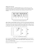
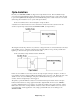
On the other hand, an Opto-Isolated circuit looks like this:
In this case, the satellite receiver relay is wired to the Opto-Coupler. The Opto-Coupler is, in effect, a
non-conductive box that contains an LED, (light emitting diode), and a photo cell. When the relay on the
satellite receiver closes, the LED lights. The photocell, imbedded in the opposite end of the box,
conducts, and the sensing IC chip is then triggered.
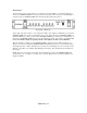
The primary operational differences between non-isolated and the Opto-Isolated circuit, is the Opto-
Isolated circuit must have a voltage applied externally to light the LED. For this reason, SMARTS
provides a small transformer power supply to provide about 12 VDC to the coupler. However, it must
NOT be there if the unit is not Opto-Isolated. Only dry contacts from the satellite receiver are used in
non-isolated units, and the application of any voltage potential will cause serious damage to the
SMARTCASTER.