
Installation manual


Engineering - 59
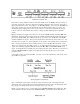
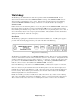
Front Panel
The front panel consists of two switches, one reset button, and several LED’s. If using the Watchdog to
monitor two SMARTCASTERS, the switch on the far left should be armed. However, if the Watchdog is
monitoring only one SMARTCASTER, this switch should be in the Disarm position.
Front Panel of Watchdog.
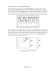
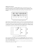
To the right of the Arm switch is a series of diagnostic LED’s. The “Monitor” LED flashes every time the
SMARTCASTER sends a pulse to the Watchdog. The “Arm” light is lit when the SMARTCASTER has
enabled the Watchdog. (There are times where SMARTCASTER cannot send pulses to the Watchdog. In
these cases, the SMARTCASTER does not “arm” the Watchdog, and the “Arm” light is off.) If, for some
reason, the “Monitor” light is not pulsing, and the “Arm” light is on, then a reset is imminent.
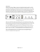
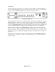
When the Watchdog actually resets the SMARTCASTER, it lights the “Reset” LED momentarily. If,
after the second try of resetting the SMARTCASTER, the Watchdog still does not receive Monitor pulses,
it then lights the “Error” LED. This light stays on until someone manually presses the reset button on the
Watchdog. In addition, the “Calling” LED will light momentarily. This signifies that the autodialer has
been tripped.
Finally, there is a power switch on the panel. For the Watchdog to monitor the SMARTCASTER, this
should always be on. In addition, it would be safer to plug the Watchdog into an Uninterruptable Power
Supply if available.