
Installation manual


Engineering - 58
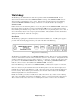
Modification in the Field
If a Watchdog is being added to a SMARTCASTER in the field, some additional steps are needed.
Included in the upgrade is a computer card, (PCL 720 - Digital I/O Card), and a wiring Harness. First,
the card needs to be installed into an empty card slot in the computer. This card sends the pulse train to
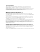
the Watchdog. Please make sure the dip switches located on the surface of the card are set to the
following:
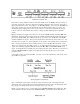
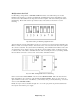
Dip Switch Setting for Watchdog Digital I/O Card
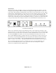
After inserting the card, the wiring Harness needs to be connected. For systems with just a Watchdog, the
Harness consists of one 20-pin connector, and two bare wires on one end, and on the other end, a 9-pin D-
sub connector is attached. For systems with both a Watchdog, and a SmartTouch, the Harness is the same
except that there are two 20-pin connectors. The 20-pin connector labeled, “CN-3” should be connected
to connector three on the surface of the PCL-720 card. The second 20-pin connector, (if existing), labeled
CN-4, should be connected to connector four on the surface of the PCL-720 card.
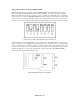
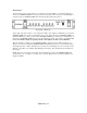
Layout for PCL 720 Digital I/O Card for Watchdog
Next, locate the button labeled RESET on the front of the SMARTCASTER. Follow the leads from the
back of this button to the connection on the motherboard labeled ‘RESET’. These two wires need to be
spliced with the two bare wires on the Harness. (A momentary short, provided by Watchdog, across these
wires resets the SMARTCASTER.)
Finally, the 9-pin connector should be brought out to one of the spare punch-out panels located between
the computer cards and the power supply.