
Installation manual


Engineering - 54
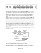
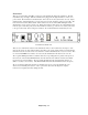
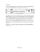
Back Panel of SmartTouch.
If the station is using satellite automation, connect the satellite feed to the Net In connection. If there is
more than one Network, connect the output of the switching equipment to this connection. Next, take a
balanced monaural air monitor, and connect it to the Air Cue terminals. Now connect the Sys. Out to an
input on the control board. Since the SmartTouch mutes the Network audio, there is no need to wire
anything through the muting relays on the 37- pin connector. Levels can be adjusted by the trim pots
located to each side of the terminal strips. (Factory settings should be 0 dB input and +4 dB audio
output.)
Plug the 24 VDC power supply in, and with power, the audio at Net In should be at the Sys. Out of the
SmartTouch. When the remote broadcast begins, the SmartTouch automatically puts the audio from the
phone line at the Sys. Out. After calling in, with the proper security code, the Air Cue or the Net In.
should be audible in the earpiece. This provides the announcer with either the station monitor or a “raw”
Network feed for cue purposes. (More explanation on the operation of the SmartTouch is provided later.)
Next, connect the audio lines from the normal production source to the Rec. In terminal strip. If the
station is recording audio from multiple sources, (i.e. production board, Network feeds, etc.), connect the
output of the switching equipment to Rec. In. Connect the Rec. Out to the SMARTCASTER record
inputs. Level adjustments are available for both recording input and output. When these connections are
made, the SMARTCASTER is capable of recording audio from either the phone line or the normal
production source.
A momentary contact closure, labeled ‘EBS’, is located on one of the terminal strips. This can be used to
trip an EBS tone generator.
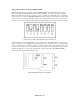
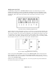
Wiring diagram for SmartTouch..
Next, a standard phone line must be connected to either of the phone jacks on the back panel of the
SmartTouch. We recommend that a non-listed, dedicated phone line be used for the SmartTouch. This
keeps people from calling the line when an announcer needs to get on the air!
Finally, a 15 pin cable needs to be connected between the SMARTCASTER and the SmartTouch. This
cable contains the data lines needed for the SMARTCASTER to communicate with the SmartTouch.